 Boats For Sale:


1969 Mustang Stringer Rebuild |
Post Reply 
|
Page <1 12131415> |
| Author | |
vondy 
Platinum Member 

Joined: November-29-2007 Location: Dallas, Texas Status: Offline Points: 1116 |
 Post Options Post Options
") Thanks(0) Thanks(0)
 Quote Reply Quote Reply
 Posted: June-30-2011 at 2:28pm Posted: June-30-2011 at 2:28pm |
|
The more I look at this the more I wonder why it would need to go to the key? Wouldn't I just need to run from the alt to the amp meter to the battery?
|
|
 |
|
|
8122pbrainard
Grand Poobah 

Joined: September-14-2006 Location: Three Lakes Wi. Status: Offline Points: 41040 |
Post Options
Thanks(0)
Quote Reply
Posted: June-30-2011 at 3:36pm |
|
David,
Take a look at this wiring diagram. Maybe it will give you a better idea rather than me trying to put it in words. But yes, aternator to te ampmeter, ampmeter to the key switch and then the key switch to accesories,ignition system and back to the start relay (solinoid) to charge the battery. It goes to the key switch so the ampmeter will indicate the total load on the charging/battery system. Keep in mind the wire gauge to the ampmeter and back to the relay neds to be rated for the alternator output. 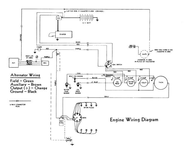
The 3rd post on the ampmeter is for the internal lighting. The case is the ground for the light. |
|
|
|
|
vondy
Platinum Member
Joined: November-29-2007 Location: Dallas, Texas Status: Offline Points: 1116 |
Post Options
Thanks(0)
Quote Reply
Posted: June-30-2011 at 4:30pm |
|
Thanks Pete, sometimes these diagrams blow my mind so see if I got this right.
I traced in red what I think I am supposed to do. The red represents my new 6 gauge wire. Alt to amp gauge. There are 3 post on the gauge, one I believe is ground. For the other two post I would connect my alt wire in and out the other to the key switch. At the key switch I could connect to the IGN post. Then would leave out of the BAT terminal back to the battery side of the solenoid. Missing anything? 
|
|
|
|
|
8122pbrainard
Grand Poobah
Joined: September-14-2006 Location: Three Lakes Wi. Status: Offline Points: 41040 |
Post Options
Thanks(0)
Quote Reply
Posted: June-30-2011 at 4:50pm |
|
David,
The red from the amp goes to the red on the key switch which is the "Batt" terminal. Leave all the rest of the wires on the key switch the same. The 3rd terminal on the amp is for lighting but should be the switched hot. The case would be the ground. Do check it out since some gauges are set up slightly different. BTW, the way you have it drawn, you would have power to the ignition all the time. Think of the key switch this way - the "bat" terminal in "IN" and all the rest are switched "OUTS". |
|
|
|
|
vondy
Platinum Member
Joined: November-29-2007 Location: Dallas, Texas Status: Offline Points: 1116 |
Post Options
Thanks(0)
Quote Reply
Posted: June-30-2011 at 4:59pm |
|
I believe a 1/4 of my wires are not original so who knows if the colors match. Probably why I'm having trouble here.
So from amp to BAT on key. Then do I go from BAT to Solenoid? |
|
|
|
|
8122pbrainard
Grand Poobah
Joined: September-14-2006 Location: Three Lakes Wi. Status: Offline Points: 41040 |
Post Options
Thanks(0)
Quote Reply
Posted: June-30-2011 at 5:27pm |
Yes but you want it connected at the solenoid to the stud where the + battery cable is connected. Don't mix it up with the small wire that energized the solenoid coil. That should be the white wire. |
|
|
|
|
vondy
Platinum Member
Joined: November-29-2007 Location: Dallas, Texas Status: Offline Points: 1116 |
Post Options
Thanks(0)
Quote Reply
Posted: June-30-2011 at 5:35pm |
|
Understood. Basically instead of connecting directly to the battery it goes to the battery via the same post on the solenoid that the battery cable is connected too.
So it's a loop, touching the gauge and ignition. It does not go in one post and out another, same post in and out, right? 
|
|
|
|
|
8122pbrainard
Grand Poobah
Joined: September-14-2006 Location: Three Lakes Wi. Status: Offline Points: 41040 |
Post Options
Thanks(0)
Quote Reply
Posted: June-30-2011 at 5:41pm |
|
No on the ampgauge. Go back to your original drawing - In one post and out the other. If they are backwards, the ampgauge will just read backwards.
|
|
|
|
|
vondy
Platinum Member
Joined: November-29-2007 Location: Dallas, Texas Status: Offline Points: 1116 |
Post Options
Thanks(0)
Quote Reply
Posted: June-30-2011 at 5:58pm |
|
Man..... OK so in one post and out the other on the amp gauge. Same post in and out on the ignition BAT. Right?
About what should my gauge be reading if everything is working correctly? I have no radio so at most the ignition, blower, bilge pump, lights.... Come to think of it, I'm not sure what the gauge goes up to. Probably not 105 amps huh? |
|
|
|
|
8122pbrainard
Grand Poobah
Joined: September-14-2006 Location: Three Lakes Wi. Status: Offline Points: 41040 |
Post Options
Thanks(0)
Quote Reply
Posted: June-30-2011 at 6:05pm |
|
David,
Alternators never put out their "rated" ouput. The output of any alternator really depends on the condition of the battery and of course the other small loads. If your battery is run down, you may peg the gauge but only for a very short time. Yes on the ignition switch. Same "bat" term in and out with the heavy wire. |
|
|
|
|
vondy
Platinum Member
Joined: November-29-2007 Location: Dallas, Texas Status: Offline Points: 1116 |
Post Options
Thanks(0)
Quote Reply
Posted: June-30-2011 at 6:12pm |
|
Pete we are lucky to have you here.

So pinging it out won't "fry" anything? I'm trying to avoid breaking anything by fixing it. |
|
|
|
|
8122pbrainard
Grand Poobah
Joined: September-14-2006 Location: Three Lakes Wi. Status: Offline Points: 41040 |
Post Options
Thanks(0)
Quote Reply
Posted: June-30-2011 at 7:02pm |
|
David,
No, it shouldn't hurt it. The ampmeter has a solid conductor post to post carrying the current. Then there's windings around it that create the magnetic field moving the needle. With a good battery that's not run down, I'd be surprised to see it hit the 40 amps. |
|
|
|
|
vondy
Platinum Member
Joined: November-29-2007 Location: Dallas, Texas Status: Offline Points: 1116 |
Post Options
Thanks(0)
Quote Reply
Posted: June-30-2011 at 7:51pm |
|
thanks Pete!
|
|
|
|
|
vondy
Platinum Member
Joined: November-29-2007 Location: Dallas, Texas Status: Offline Points: 1116 |
Post Options
Thanks(0)
Quote Reply
Posted: July-01-2011 at 11:45am |
|
Never can get quite as far as I'd like to in the time I have. This morning I started putting the engine in. Installed the flywheel then moved to the dampener. Sheared off one of the dampener bolts around 20 ft lbs. Don't know if that was too much torque or if the bolt was just too old. I'll pick up 3 new grade 8 ones at the hardware store.
When the engine tilted back, oil came out of the flywheel holes. Oops. Cleaned up easy enough. I know to seal the threads when installing but what is this extra hole for? I assume it's not open to the crank area? 


Debating on keeping these babies free of flaps.... 
|
|
|
|
|
8122pbrainard
Grand Poobah
Joined: September-14-2006 Location: Three Lakes Wi. Status: Offline Points: 41040 |
Post Options
Thanks(0)
Quote Reply
Posted: July-01-2011 at 11:55am |
|
David,
You didn't paint your wedges!! 
Go flap free. You will never get water back to the manifolds with those H/M goose neck risers. |
|
|
|
|
vondy
Platinum Member
Joined: November-29-2007 Location: Dallas, Texas Status: Offline Points: 1116 |
Post Options
Thanks(0)
Quote Reply
Posted: July-01-2011 at 12:43pm |
|
Pete I planned on painting them but first things first. Got to get this baby together if I'm going to take her on our trip first thing tomorrow morning. Man I'm cutting it close. Probably rebuilding or replacing the short block next year so I'll paint them then.
Left to do.... 1. Flywheel 2. Dampener 3. Bellhousing 4. Transmission 5. Line everything up so I can cut my exhaust hose to the proper size. 6. Figure out my shaft log hose length then put it in place. 7. Instal prop, already lapped 8. Connect remaining wires and hoses 9. Instal gas tank 10. Build side pannels 11. See if she runs |
|
|
|
|
TX Wind
Senior Member 

Joined: March-29-2011 Location: near Dallas Status: Offline Points: 333 |
Post Options
Thanks(0)
Quote Reply
Posted: July-01-2011 at 1:16pm |
|
Wow you've got a lot to do David but it's looking good. Tomorrow morning when you're finishing up, grab a quick shower to scrub the grime off and let your wife hook the trailer up while you catch a cat nap LOL.
|
|
|
|
|
vondy
Platinum Member
Joined: November-29-2007 Location: Dallas, Texas Status: Offline Points: 1116 |
Post Options
Thanks(0)
Quote Reply
Posted: July-01-2011 at 1:25pm |
|
Jeff my wife is just now getting to where she can direct me while hooking the trailer up. All you have to do is point in the direction I need to go to hook the coupling to the ball, don't see why it's so hard. At least she is getting better.
She also can't drive a stick so no chance of her driving on the trip. Not to mention she's never pulled a trailer. We should get off work early today so hopefully that will be enough time. Still wondering what's up with that extra hole in the crankshaft, should it be plugged? |
|
|
|
|
TX Wind
Senior Member
Joined: March-29-2011 Location: near Dallas Status: Offline Points: 333 |
Post Options
Thanks(0)
Quote Reply
Posted: July-01-2011 at 1:32pm |
|
Extra hole in the crankshaft? You got a pic of that?
If you're talking about the hole in the crank shaft coupler on the rear, that's probably the alignment marker. 302's are externally balanced and the flywheel has to go on using that alignment mark. |
|
|
|
|
vondy
Platinum Member
Joined: November-29-2007 Location: Dallas, Texas Status: Offline Points: 1116 |
Post Options
Thanks(0)
Quote Reply
Posted: July-01-2011 at 2:05pm |
Yes that is what I'm talking about. I was just going to bolt the flywheel on. How would I use that hole to align it? |
|
|
|
|
TX Wind
Senior Member
Joined: March-29-2011 Location: near Dallas Status: Offline Points: 333 |
Post Options
Thanks(0)
Quote Reply
Posted: July-01-2011 at 3:07pm |
|
Gosh David, I'm trying to remember here. I'm sure Pete knows this like the back of his hand or the Boat Dr. for sure. If you look at the back of the flywheel it has a counterweight. I believe the extra hole is to signify the side the counterweight goes on. You might also search some Ford 302 threads about this. If you don't get it right you will vibrate like crazy with possible disastrous results. If you haven't painted the flywheel yet, you may still be able to see how it was aligned on there by the scratches in the paint.
|
|
|
|
|
TX Wind
Senior Member
Joined: March-29-2011 Location: near Dallas Status: Offline Points: 333 |
Post Options
Thanks(0)
Quote Reply
Posted: July-01-2011 at 3:08pm |
|
Gosh David, I'm trying to remember here. I'm sure Pete knows this like the back of his hand or the Boat Dr. for sure. If you look at the back of the flywheel it has a counterweight. I believe the extra hole is to signify the side the counterweight goes on. You might also search some Ford 302 threads about this. If you don't get it right you will vibrate like crazy with possible disastrous results. If you haven't painted the flywheel yet, you may still be able to see how it was aligned on there by the scratches in the paint. Eric may know as well. He did you tranny so give him a call.
|
|
|
|
|
TX Wind
Senior Member
Joined: March-29-2011 Location: near Dallas Status: Offline Points: 333 |
Post Options
Thanks(0)
Quote Reply
Posted: July-01-2011 at 3:12pm |
|
Actually David, that's what I would do. I would call Eric. He can answer that very quickly. It could have affects on the tranny as well as the engine and I'm sure he knows.
|
|
|
|
|
Keeganino
Grand Poobah

Joined: October-27-2009 Location: North Carolina Status: Offline Points: 2063 |
Post Options
Thanks(0)
Quote Reply
Posted: July-02-2011 at 4:06am |
|
I am excited for you. Good luck this weekend. She is looking great but be patient. This final phase took a lot longer than I expected. Getting everything dialed in sounds easy till you have to do it. I spent my whole winter finishing up details that were not pertinent to getting her on the water. Remember whether you are on the water this weekend or a month from now you will have accomplished a great feat that few would dare to attempt. You make us proud!
|
|
|
"working on these old boats may not be cost effective but as it shows its what it brings into your life that matters" -Roger
1973 Skier |
|
|
|
|
vondy
Platinum Member
Joined: November-29-2007 Location: Dallas, Texas Status: Offline Points: 1116 |
Post Options
Thanks(0)
Quote Reply
Posted: July-02-2011 at 11:12am |
|
Well guys, the boat has beaten me. She will not be making the trip today. It's been a major battle, everything has been against me. Oh well, at least I'm this far along.
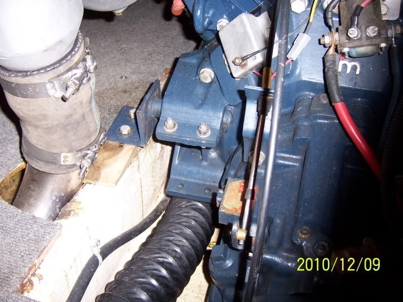
I'm at the alignment stage. Going to need to do something with the front. With my setup I have to flip my front mounts over and add wedges. If not, the front end is always too high. The new iron wedges I have are too small though. So I was going to add a block to the stringer to get it just right. So yeah Keegan, this part took way longer than expected. I actually had less trouble with the stringer job than the reassembly job. I also have an exhaust issue. Back with my old stringers, the risers where directed partly over the stringers. So the hose was bending outwards to clear it to the pipes. Well maybe it's the thicker material of my new stringers or maybe I just placed them further apart than the last but the situation is even worse. I have some new "flex" hose but it doesn't want to flex in the short length I need to connect to my fiberglass pipes. You guys got any ideas? Maybe some short metal bends like Wakeslayer has setup. Mine would be different of course with the HM risers. I guess a couple more weeks and I'll have her going. Not staying up till 3am anymore on this project. I'm considering changing out the cutlass bearing before I put everything back together. Where do I find one of those? 


|
|
|
|
|
8122pbrainard
Grand Poobah
Joined: September-14-2006 Location: Three Lakes Wi. Status: Offline Points: 41040 |
Post Options
Thanks(0)
Quote Reply
Posted: July-02-2011 at 11:24am |
|
David,
I don't see anything wrong with the way you have the front mounts set up. Take a look at wet exhaust "hump hose" connections for the hose problem. 
|
|
|
|
|
vondy
Platinum Member
Joined: November-29-2007 Location: Dallas, Texas Status: Offline Points: 1116 |
Post Options
Thanks(0)
Quote Reply
Posted: July-02-2011 at 12:49pm |
|
Thanks Pete. Sure wish you lived down the street from me

Where do you find those? |
|
|
|
|
Keeganino
Grand Poobah
Joined: October-27-2009 Location: North Carolina Status: Offline Points: 2063 |
Post Options
Thanks(0)
Quote Reply
Posted: July-02-2011 at 3:56pm |
I know exactly how you feel. When it got down to the end and it was time to align the engine, the floor was about a 1/2" too tall and we had to use a plunge router to create a recess for the mounts. The carpet was already glued down, and I had to pull it up to get in there with the router. I was feeling pretty beat up about it, but now I could care less. She runs and looks great and since we got the whole season in so far I could not be any happier. After all the time, money, and sacrifices its stressful at the end. You will figure out these last few details and next year this will all be a laugh. Go to a cookout and enjoy the Holiday weekend. You deserve it! |
|
|
"working on these old boats may not be cost effective but as it shows its what it brings into your life that matters" -Roger
1973 Skier |
|
|
|
|
Gary S
Grand Poobah

Joined: November-30-2006 Location: Illinois Status: Offline Points: 14096 |
Post Options
Thanks(0)
Quote Reply
Posted: July-02-2011 at 4:58pm |
|
I'll have to look at mine later to see how the exhaust lines up with my stringers,but here is how mine is now set up.The stainless pipe is angled in to connect up to the manifolds.
|
|
|
|
|
vondy
Platinum Member
Joined: November-29-2007 Location: Dallas, Texas Status: Offline Points: 1116 |
Post Options
Thanks(0)
Quote Reply
Posted: July-09-2011 at 10:26pm |
|
Anyone have a good shot of the side panels towards the bow end? I'm building mine now and trying to see how far forward they go and where the notches fall.
Thanks! |
|
|
|
|
Post Reply
|
Page <1 12131415> |
 Tweet
Tweet
|
| Forum Jump | Forum Permissions You cannot post new topics in this forum You cannot reply to topics in this forum You cannot delete your posts in this forum You cannot edit your posts in this forum You cannot create polls in this forum You cannot vote in polls in this forum |


 Topic Options
 vondy wrote: