 Boats For Sale:


Another BFN Rebuild |
Post Reply 
|
Page <12345 31> |
| Author | |
Okie Boarder 
Gold Member 
Joined: August-31-2009 Location: OK Status: Offline Points: 779 |
 Post Options Post Options
") Thanks(0) Thanks(0)
 Quote Reply Quote Reply
 Posted: January-03-2010 at 3:21pm Posted: January-03-2010 at 3:21pm |
|
Looking good! You're progressing a lot faster than me.
|
|
 |
|
|
WakeSlayer
Grand Poobah 

Joined: March-15-2006 Location: United States Status: Offline Points: 2138 |
Post Options
Thanks(0)
Quote Reply
Posted: January-03-2010 at 3:44pm |
|
Cool. I may give that a go. I have a couple weeks to think about it.
|
|
|
Mike N
1968 Mustang |
|
|
|
|
TRBenj
Grand Poobah

Joined: June-29-2005 Location: NWCT Status: Offline Points: 21107 |
Post Options
Thanks(0)
Quote Reply
Posted: January-04-2010 at 2:45pm |
|
Okie, not really- we've been underway since early November and we havent ordered any materials yet... youre moving much faster than us!
I would like to officially thank Greg, Gary and BJ on making me itch for another 3 days. And for almost giving me frostbite. It was a balmy 9 degrees in CT yesterday- but now I can say that the grinding is done. All wood (save for the aforementioned gunnel braces) is out of the boat- including the bow eye backer and the rudder port mount. Getting the rudder port out that had been sealed with 5200 this past summer wasnt as bad as I thought it would be- a little heat and a BFH did the job. Out in the cold: 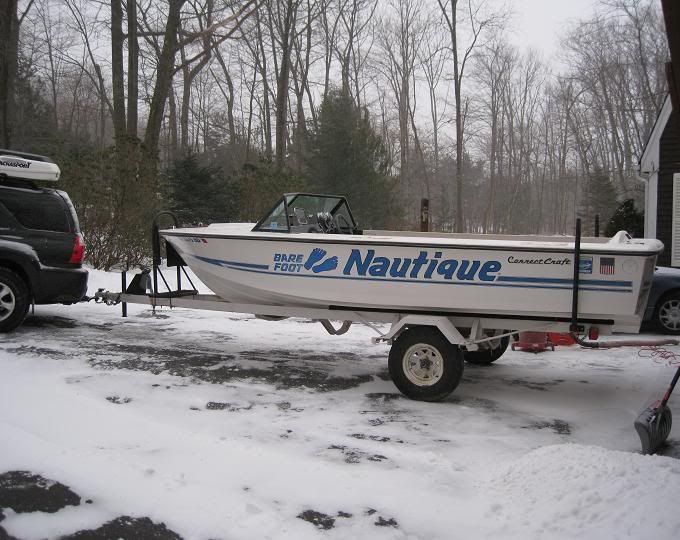
Is that dust or snow? A bit of both! 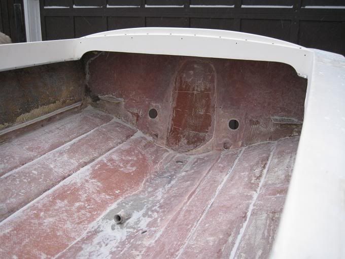
A thorough rinse with hot water created the Ice Nautique: 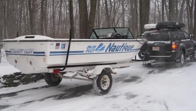
All the gel is off the hull and transom (still a little icy though): 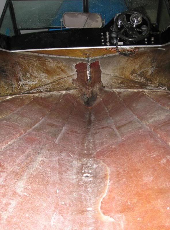
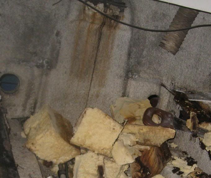
The rudder port mount: 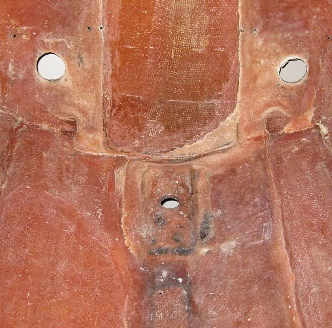
The front lifting ring area: 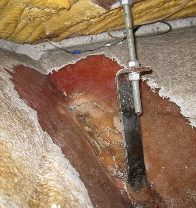
All tucked in across the back of the garage: 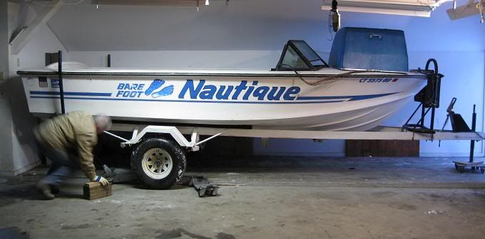
I need to confirm a few more vertical dimensions next weekend, then we can put together a decent material list and get some glass and coosa on order. |
|
|
|
|
Wacko
Senior Member 

Joined: March-21-2009 Location: BC, Canada Status: Offline Points: 293 |
Post Options
Thanks(0)
Quote Reply
Posted: January-04-2010 at 2:58pm |
|
Looking great. Excellent progress considering the weather conditions
|
|
|
|
|
Gary S
Grand Poobah

Joined: November-30-2006 Location: Illinois Status: Offline Points: 14096 |
Post Options
Thanks(0)
Quote Reply
Posted: January-04-2010 at 4:47pm |
|
Awesome Tim. I didn't realize thats how the lift eye mounts but now you'll never have to think about any old wood again.
|
|
|
|
|
Hollywood
Moderator Group

Joined: February-04-2004 Location: Twin Lakes, WI Status: Offline Points: 13510 |
Post Options
Thanks(0)
Quote Reply
Posted: January-04-2010 at 4:55pm |
|
I like how Tim is standing back taking the photos and the old man is doing the work again (remember the engine pull).
|
|
|
|
|
M3Fan
Grand Poobah

Joined: October-22-2005 Location: United States Status: Offline Points: 3185 |
Post Options
Thanks(0)
Quote Reply
Posted: January-04-2010 at 5:01pm |
|
What kind of regular expeditions/trips are you doing to facilitate DUAL cargo carriers in addition to the hauling capability of the truck? I mean honestly!
|
|
|
2000 SN GT40 w/99 Graphics/Gel
2016 SN 200 OB 5.3L DI https://forum.fifteenoff.com |
|
|
|
|
TRBenj
Grand Poobah
Joined: June-29-2005 Location: NWCT Status: Offline Points: 21107 |
Post Options
Thanks(0)
Quote Reply
Posted: January-04-2010 at 5:22pm |
|
Gary, in case my pictures dont illustrate it well, here are a few more.
From Roger (UK): 

A crappy diagram using paint: 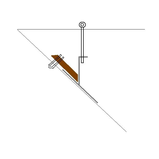
Im not sure if Roger's did or not, but the wood backing block for the bow eye extended all the way to the vertical steel portion of the lifting ring assembly on our BFN. Joel, you'd be surprised how often I use the roof boxes. I keep saying that Im going to remove them between ski seasons (I keep both snow and waterski gear up there) but I keep finding uses for them, even in the off seasons (the latest being a set of cornhole boards I built as an xmas present). Its really handy not to have to fold down the seats every time I want to move something more than a few feet long. The smaller box gets used less than the big one, but its already up there and Im already taking the aerodynamic hit, so I figure what the hell. Splitting my time between 2 states ensures that my truck is always full of gear. |
|
|
|
|
Gary S
Grand Poobah
Joined: November-30-2006 Location: Illinois Status: Offline Points: 14096 |
Post Options
Thanks(0)
Quote Reply
Posted: January-04-2010 at 5:51pm |
|
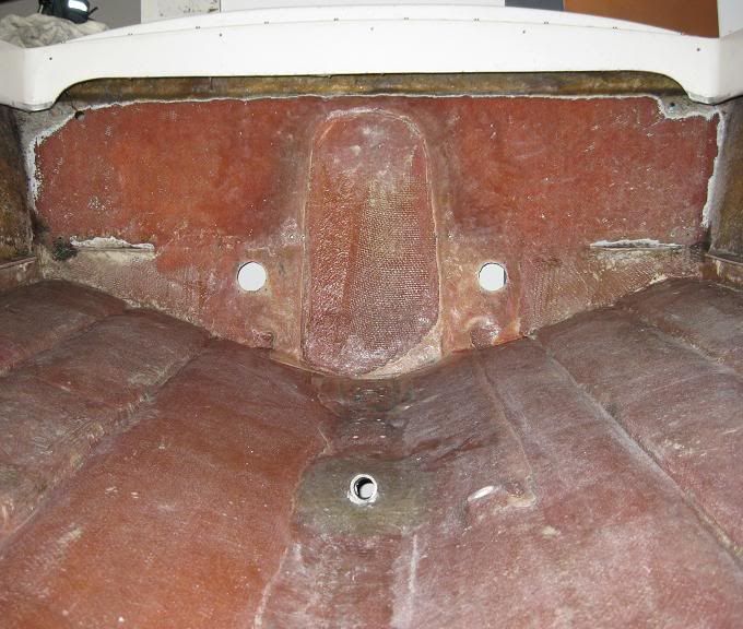
That makes it clear Tim. What was that piece of wood for in the center of the transom? Is it for the lift ring?
|
|
|
|
|
TRBenj
Grand Poobah
Joined: June-29-2005 Location: NWCT Status: Offline Points: 21107 |
Post Options
Thanks(0)
Quote Reply
Posted: January-04-2010 at 6:17pm |
|
Gary, thats correct. The wood was actually doubled up under the piece of angle iron... and boy, was it fun removing that piece of wood. Here's the best picture I have of the original assembly:
|
|
|
|
|
Gary S
Grand Poobah
Joined: November-30-2006 Location: Illinois Status: Offline Points: 14096 |
Post Options
Thanks(0)
Quote Reply
Posted: January-04-2010 at 10:47pm |
. Joel, he's got too many boats filling the garage he needs someplace to store stuff |
|
|
|
|
RainDog
Platinum Member

Joined: February-21-2007 Location: Mke/Grn Lake WI Status: Offline Points: 1387 |
Post Options
Thanks(0)
Quote Reply
Posted: January-05-2010 at 12:43am |
|
Tim - What is the significance of removing all the gel from the interior of the hull?
|
|
|
|
|
Cslaten33
Senior Member
Joined: December-21-2009 Location: Tulsa, OK Status: Offline Points: 150 |
Post Options
Thanks(0)
Quote Reply
Posted: January-05-2010 at 12:48am |
|
What should the top speed for a 74SN Skier be?
|
|
|
Thanks Clark Slaten
|
|
|
|
|
Gary S
Grand Poobah
Joined: November-30-2006 Location: Illinois Status: Offline Points: 14096 |
Post Options
Thanks(0)
Quote Reply
Posted: January-05-2010 at 1:50am |
|
Steve I think you need to do that to get a good bond. Gel is only cosmetic,plus you know Tim,by the time he's done, the bilge will be as nice as the outside.
|
|
|
|
|
TRBenj
Grand Poobah
Joined: June-29-2005 Location: NWCT Status: Offline Points: 21107 |
Post Options
Thanks(0)
Quote Reply
Posted: January-05-2010 at 12:54pm |
|
Steve, Gary is correct- you dont want to lay glass on top of the old gel. Theres no strength in it- Ive noticed its fairly brittle. Glass to glass will make a superior bond. Greg and BJ both laid fresh glass down over the hull- we may do the same in certain areas. Removing all the gel gives us unlimited options.
Clark, this isnt really the place to be asking the question, but first you need to fill us in on what youve got. I have no idea what a "SN Skier" is. Is it a Ski Nautique or a Skier? It cant be both. Which engine it has, prop, etc will all play a factor in its top speed as well. |
|
|
|
|
Mark Mel
Gold Member

Joined: September-16-2005 Location: United States Status: Offline Points: 583 |
Post Options
Thanks(0)
Quote Reply
Posted: January-05-2010 at 2:15pm |
|
Wow looks great Tim.
I use white glue to get fiberglass out of my hands. Spread on a layer, let it dry, then do another layer, let that dry. Then peel it off. It will pull most of the fiberglass out of your hands. You could do the same on your arms too, although that will pull the fur out too. You could also use duct tape although sometimes that pulls skin too. ;) |
|
|
|
|
TRBenj
Grand Poobah
Joined: June-29-2005 Location: NWCT Status: Offline Points: 21107 |
Post Options
Thanks(0)
Quote Reply
Posted: January-05-2010 at 2:18pm |
|
Thanks Mark! Are you talking like Elmers glue? Cool trick. Can I use it on my face?

|
|
|
|
|
Hollywood
Moderator Group
Joined: February-04-2004 Location: Twin Lakes, WI Status: Offline Points: 13510 |
Post Options
Thanks(0)
Quote Reply
Posted: January-05-2010 at 2:20pm |
Tim, I've got just the thing for your face. 
Mark, he gets a parafin wax at his weekly salon visits, itch should be gone by Friday. |
|
|
|
|
Mark Mel
Gold Member
Joined: September-16-2005 Location: United States Status: Offline Points: 583 |
Post Options
Thanks(0)
Quote Reply
Posted: January-05-2010 at 2:23pm |
|
Yeah Elmers, I tried titebond once but it doesn't peel off as nice.
If I had a ton in my face I'd try it, lol. The face puts up with shaving every day so a little glue can't hurt. I should market it as a mask for men. ha Imagine Melissa's face when she sees you smearing glue on your face. "Mark Mel told me to do it - I knew he was a little off" |
|
|
|
|
BuffaloBFN
Grand Poobah

Joined: June-24-2007 Location: Gainesville,GA Status: Offline Points: 6094 |
Post Options
Thanks(0)
Quote Reply
Posted: January-06-2010 at 12:07pm |
Glad to throw in my 33 cents worth! 
Looks great! |
|
|
|
|
TRBenj
Grand Poobah
Joined: June-29-2005 Location: NWCT Status: Offline Points: 21107 |
Post Options
Thanks(0)
Quote Reply
Posted: January-13-2010 at 9:10pm |
|
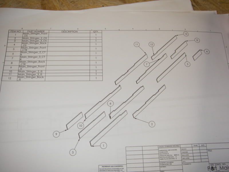
I took some depth measurements this weekend so I was able to lay out a rough cross section for the ribs and bulkheads. Not much holding us back from ordering materials now.
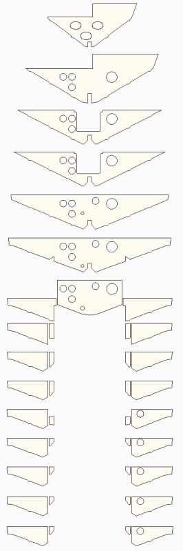
When I did the cross section of the stringers, I realized that with the taller primaries required by the new engine cradle (without cutting it up, anyways), I realized that the exhaust hoses wouldnt fit between them and the floor if left full height over their entire length. So, I cut them down behind the engine to closer to stock level. No need to waste material there anyways, I suppose. In order to clear where the exhaust hoses enter the bilge, I think the stringers and cradle will have to be notched at the top. The plan is to run 4" hose. 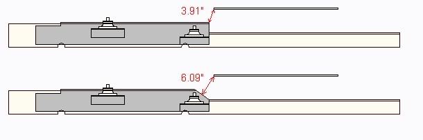
I also have a plan for the battery box drain. Im not crazy about having clamped connections below the floor, so I want to use PVC here as well. A few 22 degree elbows installed between the middle bulkheads should give me some slope so that it self drains. 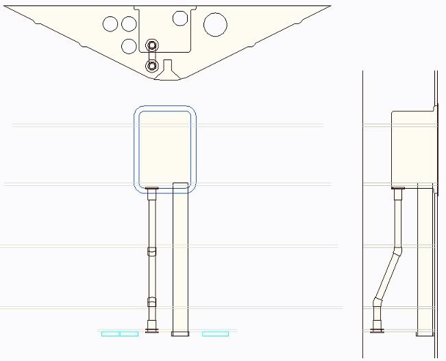
We've come to the conclusion that no matter what, its almost inevitable that water will find its way under the floor- superior construction techniques and all. Therefore, Im leaving provisions to get the water back out. Like many here have done in the past (namely Joe in his '83), the under floor area will drain together via cut outs in the ribs where they join the secondaries. The front bulkheads will have notches where they join the keel board. Right now, the only compartments that self drain (to the bilge) are the ones on either side of the engine (note the half moon drains in the primaries). Since we want to through bolt the cradle instead of lagging it, the floor over the primaries cant be installed until after the cradle is in- so getting them sealed off from the top would be problematic. Everything else is sealed off from these, and there are 3 strategically placed access points to drain the subfloor area, should water ever get in. There will be no floor from the rearmost ribs back (essentially the last 10", under the gas tank), so any water in these 2 rear cavities can be reached with a pump if the nose of the boat is raised. To remove any water that collects at the low point of the hull in front, a 6" port will be installed on the front wall of the battery box. Right now, I think the access hole will be capped with an inspection plate similar to the one used over the driveshaft packing nut. |
|
|
|
|
Mark Mel
Gold Member
Joined: September-16-2005 Location: United States Status: Offline Points: 583 |
Post Options
Thanks(0)
Quote Reply
Posted: January-13-2010 at 10:27pm |
|
Are you going to CNC those bulkheads/ribs?
|
|
|
|
|
TRBenj
Grand Poobah
Joined: June-29-2005 Location: NWCT Status: Offline Points: 21107 |
Post Options
Thanks(0)
Quote Reply
Posted: January-13-2010 at 10:33pm |
|
I wish! No, each piece of the structure will be cut by hand... the hull is far from consistent so there will be small variations everywhere to get the final product straight and level.
|
|
|
|
|
Keuka
Senior Member

Joined: October-15-2009 Location: Keuka Lake, NY Status: Offline Points: 162 |
Post Options
Thanks(0)
Quote Reply
Posted: January-13-2010 at 10:36pm |
|
Tim
To help with the water draining, would it be beneficial to add a drain plug on the low point in the center of the transom? It looks like you are planning relief cuts to allow the water to run all the way back. David |
|
|
|
|
TRBenj
Grand Poobah
Joined: June-29-2005 Location: NWCT Status: Offline Points: 21107 |
Post Options
Thanks(0)
Quote Reply
Posted: January-13-2010 at 11:08pm |
David, thanks for the thought. The idea is to give the water a way out, without giving it an obvious way in. This is why Im keeping everything seperate from the bilge, for the most part. The manual drain points would be here: 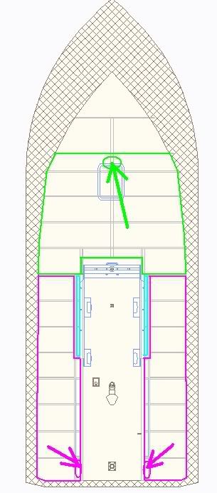
The 2 rear side cavities (purple) drain to the back (but not to the bilge). The front cavity (green) will be collected at the low point in front of the battery box. The light blue areas will drain to the bilge. The front 2 cavities will be foamed (to hold the pipes in place and give me a little time before the boat goes to the bottom of the lake) and will be sealed off. I suppose I could put drain plugs in the bottom or transom in those 3 locations, but I dont think its necessary. Not much water should collect below the floor, so draining these cavities shouldnt be a regular occurance... more like a fail safe. Im thinking once or twice a year. For those times, a hand pump should work just fine. Im not too crazy about having to drill extra holes in the boat either! |
|
|
|
|
Keeganino
Grand Poobah

Joined: October-27-2009 Location: North Carolina Status: Offline Points: 2063 |
Post Options
Thanks(0)
Quote Reply
Posted: January-13-2010 at 11:34pm |
These diagrams are great, but since I am new to this could you please explain the holes in the bulkheads? Why it goes from three big ones to down to the end where there are 4 on the left and 2 on the right... I know this is probably common knowledge to all yall salty dawgs but it would help me understand the flow and layout. Thanks Keegan |
|
|
|
|
RainDog
Platinum Member
Joined: February-21-2007 Location: Mke/Grn Lake WI Status: Offline Points: 1387 |
Post Options
Thanks(0)
Quote Reply
Posted: January-14-2010 at 12:11am |
|
Tim, You should really consider planning out your projects instead of hacking into it with out thinking it through...
|
|
|
|
|
JoeinNY
Grand Poobah

Joined: October-19-2005 Location: United States Status: Offline Points: 5693 |
Post Options
Thanks(0)
Quote Reply
Posted: January-14-2010 at 1:28am |
At prices around 250 for a 4x8 sheet, you don't want to just start cutting that coosa without a plan... 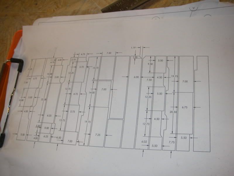
Coosa first claimed they would CNC cut the pieces for me... then backed out.. too bad it would have saved a lot of cutting. Tim I ended up using a Jigsaw for most of the cutting to keep the dust at a minimum. I started off thinking a Zip saw would be the ticket but it was more trouble that it was worth even after acquiring various guides it was not easy to ever get a straight line, and it generated more dust. I went through a good sized pack of assorted dewalt jig saw blades, the coosa was surprisingly hard on them. |
|
|
|
|
critter
Platinum Member

Joined: January-11-2008 Location: New Hill, NC Status: Offline Points: 1227 |
Post Options
Thanks(0)
Quote Reply
Posted: January-14-2010 at 1:38am |
|
Joe, what about a 4 1/2" grinder with a cutoff wheel in it ? Would that cut about as good as a jigsaw ? It should be faster and then use a jigsaw on the inside corners.
|
|
|
1980 Ski Nautique
1966 Barracuda |
|
|
|
|
lfskizzer
Senior Member

Joined: July-26-2007 Location: Wilton, CT Status: Offline Points: 290 |
Post Options
Thanks(0)
Quote Reply
Posted: January-14-2010 at 2:06am |
|
when we cut out our pieces for the stringers we used a table saw to rip the boards, sistered them up 1/2" 3/4" and 1/2" switching back and forth 5' 1" and 8' either or to get 13'1" for the Mains, then we traced them with the original stringers and jig sawed them. Then we used a planner to put the angles to somewhat match up to the hull.
critter a grinder would create alot of dust. with the table saw we attached a vacuum to the shoot out so the dust was to a minimal. Hey Tim you guys working on the boat this weekend? I might be bored saturday lol as im not going to VT this weekend. |
|
|
|
|
Post Reply
|
Page <12345 31> |
 Tweet
Tweet
|
| Forum Jump | Forum Permissions You cannot post new topics in this forum You cannot reply to topics in this forum You cannot delete your posts in this forum You cannot edit your posts in this forum You cannot create polls in this forum You cannot vote in polls in this forum |


 Topic Options
 M3Fan wrote: