 Boats For Sale:


PCM 351W fresh water cooling (FWC) |
Post Reply 
|
Page 123> |
| Author | ||
Wilhelm Hertzog 
Senior Member 
Joined: June-14-2014 Location: Cape Town Status: Offline Points: 327 |
 Post Options Post Options
") Thanks(0) Thanks(0)
 Quote Reply Quote Reply
 Topic: PCM 351W fresh water cooling (FWC) Topic: PCM 351W fresh water cooling (FWC)Posted: December-31-2021 at 9:31am |
|
|
Wrapping up this thread: the impeller change did not change much as far as engine temps or bucket test results go. I've decided to live with the slightly high (by marine standards - but seemingly acceptable by automotive standards) operating temps.
|
||
|
1982 Ski Nautique PCM351W RR II Velvet Drive 10-17-003 1:1 II PerfectPass Stargazer
Do not go gentle into that good night. Rage, rage against the dying of the light. |
||
 |
||
|
Wilhelm Hertzog
Senior Member
Joined: June-14-2014 Location: Cape Town Status: Offline Points: 327 |
Post Options
Thanks(0)
Quote Reply
Posted: May-23-2021 at 3:01pm |
|
Yes I do - it is installed on my engine. It took quite a bit of searching around to get everything together for the fresh water cooling conversion I did in 2019. Rudy Solares at Marine Parts Guys eventually managed to get everything together for me (after a lot of to and fro with PCM from his side). Bottom line: I could not order R025004 as an individual part. PCM (via Rudy) eventually gave me one part number (RA025009) to order which included (or replaced) all of the following items: 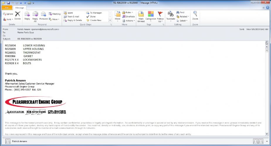 My understanding at the time was that there had been a problem with the sealing of the thermostat in the thermostat housing, so the thermostat housing was redesigned and the old one (R025004) discontinued. I'm not sure of the part number for just the lower housing that was included in my RA025009, and whether the lower housing included with RA025009 will work with the old upper housing (R025009 or RB025009). I guess SkiDim or someone like Marine Parts Guys should be able to get the answer out of PCM for you (PCM doesn't like dealing directly with the public - they told me as much via Rudy).
|
||
|
1982 Ski Nautique PCM351W RR II Velvet Drive 10-17-003 1:1 II PerfectPass Stargazer
Do not go gentle into that good night. Rage, rage against the dying of the light. |
||
|
||
|
Singlespeedy
Newbie 
Joined: June-08-2018 Location: 83864 Status: Offline Points: 6 |
Post Options
Thanks(0)
Quote Reply
Posted: May-23-2021 at 11:36am |
|
|
Do you still have the lower thermostat housing R025004? Mine is cracked and I'm searching!
|
||
|
||
|
SNobsessed
Grand Poobah 
Joined: October-21-2007 Location: IA Status: Offline Points: 7102 |
Post Options
Thanks(0)
Quote Reply
Posted: November-24-2020 at 9:28pm |
|
|
OK sorry for bad info, it must be a different pump than I had. Mine would only go together 1 way. Maybe it was machined wrong but it is a fact.
|
||
|
“Beer is proof that God loves us and wants us to be happy.”
Ben Franklin |
||
|
||
|
KENO
Grand Poobah
Joined: June-06-2004 Location: United States Status: Offline Points: 10650 |
Post Options
Thanks(0)
Quote Reply
Posted: November-24-2020 at 5:54pm |
|
I think what you really mean to say is that the holes are indeed 120 degrees apart and the housing can go on 3 different ways but only one way works to have the suction and discharge facing straight up and down on a PCM pump bracket  Wilhelm took some really good, clear pictures and you could measure the distance between the 3 holes and see that they're 120 degrees apart on the bearing housing, the impeller housing and the gasket.. Or I could mention that I just put one together 3 different ways
|
||
|
||
|
SNobsessed
Grand Poobah
Joined: October-21-2007 Location: IA Status: Offline Points: 7102 |
Post Options
Thanks(1)
Quote Reply
Posted: November-24-2020 at 1:11pm |
|
|
The housing only goes together 1 way, as the holes are not exactly 120 deg apart. I would just scrape off the crud, put a new PCM impeller in it, & not look back.
|
||
|
“Beer is proof that God loves us and wants us to be happy.”
Ben Franklin |
||
|
||
|
KENO
Grand Poobah
Joined: June-06-2004 Location: United States Status: Offline Points: 10650 |
Post Options
Thanks(1)
Quote Reply
Posted: November-24-2020 at 7:55am |
|
|
To me, the cam looks good, it's symmetrical and can go in either way.
The O ring goes on one side of the plate and gasket on the other just like the diagram shows. Pete will probably say that impeller is good for another quarter of a century or so...........I'd replace it anyways since you're having cooling issues
|
||
|
||
|
Wilhelm Hertzog
Senior Member
Joined: June-14-2014 Location: Cape Town Status: Offline Points: 327 |
Post Options
Thanks(0)
Quote Reply
Posted: November-24-2020 at 2:01am |
|
|
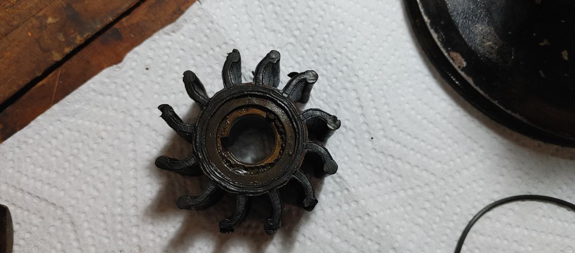
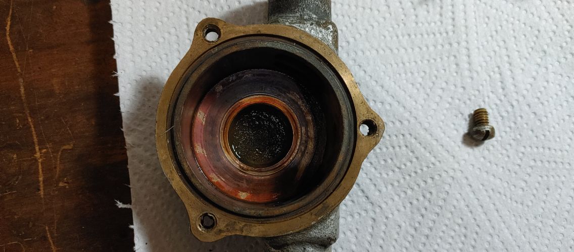
Below are pictures of my disassembled raw water pump. The impeller clearly is not in the best of shape anymore, so hopefully changing that will improve water flow/priming at low engine speeds.
Three questions I'd really appreciate some help with:
        |
||
|
1982 Ski Nautique PCM351W RR II Velvet Drive 10-17-003 1:1 II PerfectPass Stargazer
Do not go gentle into that good night. Rage, rage against the dying of the light. |
||
|
||
|
Wilhelm Hertzog
Senior Member
Joined: June-14-2014 Location: Cape Town Status: Offline Points: 327 |
Post Options
Thanks(0)
Quote Reply
Posted: November-16-2020 at 6:35am |
|
Yes, I'm confident the plumbing is correct. I'll change the impeller and report back. |
||
|
1982 Ski Nautique PCM351W RR II Velvet Drive 10-17-003 1:1 II PerfectPass Stargazer
Do not go gentle into that good night. Rage, rage against the dying of the light. |
||
|
||
|
8122pbrainard
Grand Poobah

Joined: September-14-2006 Location: Three Lakes Wi. Status: Offline Points: 41040 |
Post Options
Thanks(0)
Quote Reply
Posted: November-16-2020 at 5:19am |
|
I really don't feel it would help the cooling problem. Have you double checked how you have the engine plumbed?
|
||
|
||
|
Wilhelm Hertzog
Senior Member
Joined: June-14-2014 Location: Cape Town Status: Offline Points: 327 |
Post Options
Thanks(0)
Quote Reply
Posted: November-16-2020 at 4:03am |
|
|
As I noted in this thread, my boat's ventilation system was totally butchered at some point. As part of this process, the front vents were sealed off, so it seems to me there is very limited flow of fresh air getting to the engine under normal operating conditions. Could improving engine ventilation improve engine temperatures in any meaningful way?
|
||
|
1982 Ski Nautique PCM351W RR II Velvet Drive 10-17-003 1:1 II PerfectPass Stargazer
Do not go gentle into that good night. Rage, rage against the dying of the light. |
||
|
||
|
Wilhelm Hertzog
Senior Member
Joined: June-14-2014 Location: Cape Town Status: Offline Points: 327 |
Post Options
Thanks(0)
Quote Reply
Posted: November-12-2020 at 6:35pm |
|
|
Before realising there were air leaks in the raw water circuit I was thinking the impeller was to blame for my issues, so I ordered a new one. Because my bucket test results were far better after the air leaks were fixed (definitely emptied a 5 gallon bucket in less than a minute at idle) I never installed the new impeller. But I'll install it and see if that makes a difference.
|
||
|
1982 Ski Nautique PCM351W RR II Velvet Drive 10-17-003 1:1 II PerfectPass Stargazer
Do not go gentle into that good night. Rage, rage against the dying of the light. |
||
|
||
|
KENO
Grand Poobah
Joined: June-06-2004 Location: United States Status: Offline Points: 10650 |
Post Options
Thanks(1)
Quote Reply
Posted: November-12-2020 at 1:50pm |
|
|
Logically, if you have no idea what the Raw Water Pump impeller or the inside of the pump looks like or how old it is, that would be a good place to start.
You have a bunch of money invested in new cooling system parts, why not spend a little more on a new impeller? The worst thing that can happen is that you'll have a spare impeller and that's not exactly a bad thing. Here's a link to a Sherwood catalog that has impeller performance curves on page 10. Your G20 or 21 pump with a 9959K impeller should empty a 5 gallon bucket in under a minute at about 1000 rpm if you want to compare your test results to their graph. If you have a different Sherwood pump, you should be able to find it's info in the same catalog. Then you could figure out what you have for an engine circulating pump as the next step if necessary
|
||
|
||
|
Wilhelm Hertzog
Senior Member
Joined: June-14-2014 Location: Cape Town Status: Offline Points: 327 |
Post Options
Thanks(0)
Quote Reply
Posted: November-12-2020 at 8:25am |
|
|
No, I didn't. It is the OEM heat exchanger from PCM, and as best I can tell nothing in my engine should make it need a larger heat exchanger. So I figured I'll revisit that as a last resort if I've exhausted all other troubleshooting options.
At the moment I'm leaning towards replacing the impeller to see if that makes a difference. The impeller looks fine when inspected through the pump outlet, but I'm not sure how old it is (which probably means it's quite old), and maybe it's bucket test performance is not quite as good as it should be, which just may be enough to tip the engine into overheating and not maintaining a stable temperature? If replacing the impeller doesn't help, then maybe there's an issue with my circulation pump not circulating water through the engine well enough? |
||
|
1982 Ski Nautique PCM351W RR II Velvet Drive 10-17-003 1:1 II PerfectPass Stargazer
Do not go gentle into that good night. Rage, rage against the dying of the light. |
||
|
||
|
8122pbrainard
Grand Poobah
Joined: September-14-2006 Location: Three Lakes Wi. Status: Offline Points: 41040 |
Post Options
Thanks(0)
Quote Reply
Posted: November-12-2020 at 7:58am |
|
|
Wilhelm,
Did you ever investigate potential issue with the size of the heat exchanger?
|
||
|
||
|
Wilhelm Hertzog
Senior Member
Joined: June-14-2014 Location: Cape Town Status: Offline Points: 327 |
Post Options
Thanks(0)
Quote Reply
Posted: November-12-2020 at 3:47am |
|
|
Okay, so a follow up after doing the following over the past few months:
Engine temps were fine on a hose in the garage (I could not run it for extended periods on the hose though), but when I took it out for its first water test a few days ago, engine temperatures were still running up (to about 190 - and rising - on my IR temp gun) when the motor is at idle for long periods of time and when coming down to idle rpm after running at speed. At speed, and also when revving the motor in neutral to about 2,000 rpm the engine temp drops quickly back to normal (170 and below - I have a 170 deg. thermostat). So it seems to me the raw water pump is not circulating enough raw water through the heat exchanger at idle speeds. Is this a common problem with fresh water cooled setups like mine? I imagine not. Other than replacing the impeller and seeing if that gives me (even) better results on a bucket test, I can't think of anything else to improve the situation. Any suggestions?
|
||
|
1982 Ski Nautique PCM351W RR II Velvet Drive 10-17-003 1:1 II PerfectPass Stargazer
Do not go gentle into that good night. Rage, rage against the dying of the light. |
||
|
||
|
Wilhelm Hertzog
Senior Member
Joined: June-14-2014 Location: Cape Town Status: Offline Points: 327 |
Post Options
Thanks(0)
Quote Reply
Posted: May-19-2020 at 7:13am |
|
Finally figured out what manifolds and risers I have: link. They are the Chevy ones though, hence the adapter plate as mentioned in some of the later posts. Interesting mix I have here: New Zealand manifolds on an American boat in South Africa. 
|
||
|
1982 Ski Nautique PCM351W RR II Velvet Drive 10-17-003 1:1 II PerfectPass Stargazer
Do not go gentle into that good night. Rage, rage against the dying of the light. |
||
|
||
|
Wilhelm Hertzog
Senior Member
Joined: June-14-2014 Location: Cape Town Status: Offline Points: 327 |
Post Options
Thanks(0)
Quote Reply
Posted: January-10-2020 at 5:40pm |
|
I have a dripless shaft seal. Where in this path should the water feed to the shaft seal ideally be located? And is it okay to run the engine in gear on a flushing connection with a dripless seal (bearing is lubricated with the water feed?) or will that destroy the cutlass bearing? |
||
|
1982 Ski Nautique PCM351W RR II Velvet Drive 10-17-003 1:1 II PerfectPass Stargazer
Do not go gentle into that good night. Rage, rage against the dying of the light. |
||
|
||
|
Gary S
Grand Poobah

Joined: November-30-2006 Location: Illinois Status: Offline Points: 14096 |
Post Options
Thanks(0)
Quote Reply
Posted: January-02-2020 at 1:59am |
|
|
Up to you if you change them Correct Craft seems that now days they only use that grey plastic. If your in salt,which I think the reason you have the fresh water cooling, and you want to change you don't want brass you'll want bronze
|
||
|
||
|
Wilhelm Hertzog
Senior Member
Joined: June-14-2014 Location: Cape Town Status: Offline Points: 327 |
Post Options
Thanks(0)
Quote Reply
Posted: January-02-2020 at 1:22am |
|
|
Should I replace the plastic tees and elbows in the system with brass while I'm at it? Or is plastic fine?
|
||
|
1982 Ski Nautique PCM351W RR II Velvet Drive 10-17-003 1:1 II PerfectPass Stargazer
Do not go gentle into that good night. Rage, rage against the dying of the light. |
||
|
||
|
outerbanked
Senior Member
Joined: July-27-2017 Location: seattle Status: Offline Points: 104 |
Post Options
Thanks(1)
Quote Reply
Posted: December-30-2019 at 2:00am |
|
|
I know you have a few issues you are working on. Agree with KENO to simplify what you have until it is working. Get an infrared temp gun.
1. Create a block diagram of your system. 2. Your heater should be on the antifreeze circuit. (Warmer heat, ability to help cool your engine using it). 3. Have you been able to verify both of your pumps are working? a. Part number for your engine mount water pump is a bi-directional marine pump? b. Raw water pump has sufficient flow. 4. Your path should be water inlet, strainer, trans cooler, raw water pump, heat exchanger, tee, exhaust manifolds. Pg55. https://www.marinepartsguys.com/wp-content/uploads/ILLUSTRATED-PARTS-MANUAL-PCMcompressed.pdf |
||
|
||
|
KENO
Grand Poobah
Joined: June-06-2004 Location: United States Status: Offline Points: 10650 |
Post Options
Thanks(1)
Quote Reply
Posted: December-29-2019 at 7:47pm |
|
|
#1 Why not keep it simple till you get things figured out and disconnect the heater or at least isolate it?
#2 The transmission cooler is usually the first place the cool water goes. Some setups have the cooler before the raw water pump and others have it after the raw water pump but in either case, the first thing to get cooled is the transmission fluid. In the link is a "typical closed water cooling half system" like yours. It's for an inboard outboard and shows the raw water going through a power steering cooler after the transmission cooler, but you'll see the typical flow path. link |
||
|
||
|
Wilhelm Hertzog
Senior Member
Joined: June-14-2014 Location: Cape Town Status: Offline Points: 327 |
Post Options
Thanks(0)
Quote Reply
Posted: December-29-2019 at 6:32pm |
|
The pictures below shows the detail. Raw water leaves the heat exchanger to the T circled in blue. From there I assume it is supposed to flow to the next T circled in green (more clearly visible in the second photo). This T sends water to the exhaust manifolds and the trans oil cooler. From the trans oil cooler, water is sent to a heater I have mounted in the front of the boat. Water from the heater comes back to the blue T via the red elbow connector. Upon looking at this setup, a few things here don't make sense to me the way the guys who did the installation for me did things: 1. Water coming out the heat exchanger and water coming back from the heater will be 'fighting' each other at the blue T, not so? Surely this will create flow issues somewhere? The heater never heated up properly despite the engine running hot - a symptom of this perhaps? 2. Having raw water pass through the heat exchanger before going to the trans oil cooler must surely mean the trans oil cooler is not getting particularly cool water? The standard placement would be before the heat exchanger, right? Even though this means the trans oil cooler is putting some heat into the water going into the heat exchanger? Thanks for any help here!  
|
||
|
1982 Ski Nautique PCM351W RR II Velvet Drive 10-17-003 1:1 II PerfectPass Stargazer
Do not go gentle into that good night. Rage, rage against the dying of the light. |
||
|
||
|
KENO
Grand Poobah
Joined: June-06-2004 Location: United States Status: Offline Points: 10650 |
Post Options
Thanks(0)
Quote Reply
Posted: December-21-2019 at 1:04pm |
|
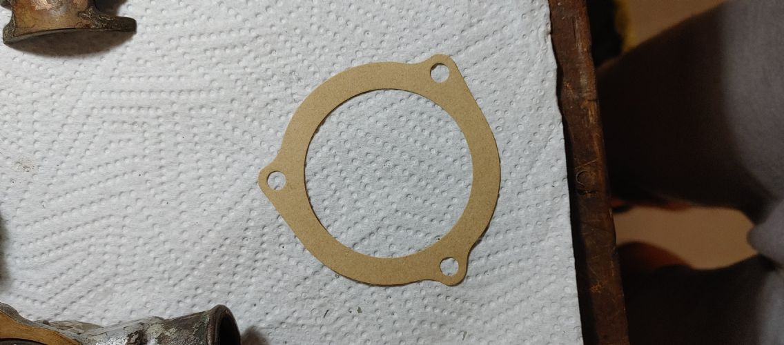
I figure if you start with a marine manifold for a 5.3 or 6.0 Chevy, a sandwich type adapter plate that would probably have to be "home grown" would make this halfway easy Here'a a picture of a 6.0 Chevy exhaust gasket and a 351w exhaust gasket, you'll have to visualize the adapter plate. I think a machinist in South Africa or anywhere else could whip up a couple of those adapters fairly easily 
|
||
|
||
|
JoeinNY
Grand Poobah

Joined: October-19-2005 Location: United States Status: Offline Points: 5693 |
Post Options
Thanks(0)
Quote Reply
Posted: December-20-2019 at 1:20pm |
|
|
So if it is reverse rotation it may actually need a bidirectional circulation pump to work correctly, Something has to move that water through the heat exchanger. Considering the number of automotive parts needed to make things work over there I would check to make sure a standard rotation automotive pump wasn't used.
It is important that the heat exchanger is plumbed in the correct location to get full capacity out of the heat exchanger but near as I can tell it is. I would love to see how they got a chevy manifold to fit a ford. |
||
|
||
|
Gary S
Grand Poobah
Joined: November-30-2006 Location: Illinois Status: Offline Points: 14096 |
Post Options
Thanks(0)
Quote Reply
Posted: December-20-2019 at 11:59am |
|
|
Oh - never mind. According to the Shamrock guys these parts can be mounted just about anywhere but they are not to concerned at how anything looks,just that it does the job.
|
||
|
||
|
TRBenj
Grand Poobah

Joined: June-29-2005 Location: NWCT Status: Offline Points: 21109 |
Post Options
Thanks(0)
Quote Reply
Posted: December-20-2019 at 11:45am |
|
I know how it’s supposed to be plumbed, I’m asking how he has it plumbed since there appear to be a number of inconsistencies to go along with the described cooling problem.
|
||
|
||
|
GottaSki
Grand Poobah
Joined: April-21-2005 Location: NE CT Status: Offline Points: 3327 |
Post Options
Thanks(0)
Quote Reply
Posted: December-20-2019 at 11:45am |
|
|
I think the vacuum advance is inhibiting water flow
What happens if you remove the statat? that could tell you if you have a enough heat transfer available in the system, and suggest which water circuit the problem is. |
||
|
"There is nothing, absolutely nothing, half so much worthwhile as messing around with boats...simply messing."
River Rat to Mole |
||
|
||
|
Gary S
Grand Poobah
Joined: November-30-2006 Location: Illinois Status: Offline Points: 14096 |
Post Options
Thanks(0)
Quote Reply
Posted: December-20-2019 at 11:36am |
|
I'd like to know where the water comes from before that T to the manifolds i.e. Is the raw water making a full pass through the exchanger not tapped off half way down it or something. I just cannot see where it is coming from in the pictures |
||
|
||
|
Gary S
Grand Poobah
Joined: November-30-2006 Location: Illinois Status: Offline Points: 14096 |
Post Options
Thanks(0)
Quote Reply
Posted: December-20-2019 at 11:32am |
|
Tim the raw water from the hull pickup follows the normal PCM path until it exits out of the Sherwood pump. Instead of running to the thermostat housing it goes to the heat exchanger cooling the block coolant then exits out of exchanger via 1 outlet into that T and then like a raw water cooled engine into each exhaust manifold through the risers and out. They put the water in the back of the manifolds only because the way the exchanger is mounted its outlet is near the bellhousing thus keeping the hose length short. The only real difference here is that he has the exchanger mounted across the rear of the engine rather than PCM's length wise mount behind the Sherwood pump. This is why it is called a half system in the sence that only the block is protected- the manifolds still being raw water. I'm not sure but I think a full system has the manifolds cooled by the block water with block off plates at the manifold to riser joint but the risers are still cooled by the exit of the raw water |
||
|
||
|
Post Reply
|
Page 123> |
 Tweet
Tweet
|
| Forum Jump | Forum Permissions You cannot post new topics in this forum You cannot reply to topics in this forum You cannot delete your posts in this forum You cannot edit your posts in this forum You cannot create polls in this forum You cannot vote in polls in this forum |


")


 Topic Options
 Singlespeedy wrote: