 Boats For Sale:


db electrical alternator |
Post Reply 
|
Page 123> |
| Author | |||
nuttyskier2002 
Gold Member 
Joined: September-28-2005 Location: United States Status: Offline Points: 669 |
 Post Options Post Options
") Thanks(0) Thanks(0)
 Quote Reply Quote Reply
 Topic: db electrical alternator Topic: db electrical alternatorPosted: April-21-2008 at 3:09pm |
||
Skalomenos, I'm pretty sure that the black and green wires are not necessary any more with your one wire alt. The one wire does not need an excitation circuit as this is done inside the alt. For now, just tape up ends of these two wires (temporarily and separately of course) and start your engine. Check that all your gages and accessories are working normally. Make sure you are charging. If you don't have a voltmeter installed, I would install one (in place of the amp meter that is). If everything works normally you can do away with the other two wires. One question - do the black and green wires join your wiring harness bundle and disappear? |
|||
|
95 Malibu Echelon w/Mercruiser 350 Magnum Skier
Former boats: 88 Ski Centurion Tru Trac II 59 Chris Craft Capri (woody) |
|||
 |
|||
|
skalomenos
Newbie 
Joined: February-19-2008 Location: United States Status: Offline Points: 2 |
Post Options
Thanks(0)
Quote Reply
Posted: April-20-2008 at 5:04pm |
||
|
Can anyone offer any help in regards to wiring? I am going from a three wire Mando alternator to a one wire Delco alternator. I know where the battery wire connects but I am stuck wondering what to do with the other wires. I have a black..I suppose this is the ground and then I have a green wire I think was connected to the exciter? I need help regarding what needs to be done with the green and black wires now.
|
|||
|
-Nothing beats a day on the water
|
|||
|
|||
|
79nautique
Grand Poobah 

Joined: January-27-2004 Location: United States Status: Offline Points: 7872 |
Post Options
Thanks(0)
Quote Reply
Posted: February-22-2008 at 4:09pm |
||
well if that happens then you just learned a valuable lesson as to why you do not remove the fuse or curcuit breaker from the curcuit. Because if it does short then it will blow the fuse or trip the breaker depending what is used. So I'm going to double the output of the alt so I better change all of the wiring going to the dash. No not true, might have to change the wire from the alternator to the first connection where it is attached to the battery cable. But not the dash you haven't done anything to it to change the load going to it that would increase the load or increase the current draw. Oh but I'm going to add a killer system and some ballast tanks. Oh really cool you just added 10 amps more current by doing that so now when I flip everything on that is on the dash it will draw 30 amps instead of 20 amps. So if that 10 gauge wire is too small to handle the extra current it was marginal to start with and should have been a larger gauge from the get go. So if you want to waiste your time and money re-wiring the boat knock your self out but all you need to change is one section of wire that is maybe 5' long because you are not changing any electrical load on the sytem by just upgrading the alternator. And even if you are adding pumps and a head unit you are barely increasing the load on the system at the dash but I've got amps big deal they should be connected directly to the battery to start with and the increased wire size from the alternator to the solenoid/relay takes care of that and the extra battery easily. |
|||
|
|||
|
05 210
Platinum Member

Joined: February-17-2006 Location: Southern Maine Status: Offline Points: 1481 |
Post Options
Thanks(0)
Quote Reply
Posted: February-21-2008 at 10:08pm |
||
|
I got it Tim! Before reading all the above posts.In a perfect world,you don't need to upgrade the wiring,but if you were to get a short(high current demand)on that wire......ssssmmmokin!I knew the answer was right in front of me,it was just easier to ask you
 . You can hook 10ga jumper cables to your dead car battery no problem,but try to start the car and see what happens. I misunderstood you earlier cause I didn't realize that schematic was modified. . You can hook 10ga jumper cables to your dead car battery no problem,but try to start the car and see what happens. I misunderstood you earlier cause I didn't realize that schematic was modified.
Mike. |
|||
|
|||
|
8122pbrainard
Grand Poobah

Joined: September-14-2006 Location: Three Lakes Wi. Status: Offline Points: 41040 |
Post Options
Thanks(0)
Quote Reply
Posted: February-21-2008 at 10:07pm |
||

|
|||
|
|||
|
Jim_In_Houston
Platinum Member
Joined: September-06-2004 Location: United States Status: Offline Points: 1120 |
Post Options
Thanks(0)
Quote Reply
Posted: February-21-2008 at 10:01pm |
||
|
I still think I can piss farther than anyone else.
|
|||
|
Happy owner of a '66 and a '68 Mustang
|
|||
|
|||
|
dans
Senior Member 
Joined: March-23-2006 Location: United States Status: Offline Points: 187 |
Post Options
Thanks(0)
Quote Reply
Posted: February-21-2008 at 8:20pm |
||
|
The fuse is cheap . The wire is not very expensive. About 20 minutes to wire it all up. Protect your boat for a few bucks , NO BRAINER.
|
|||
|
|||
|
eric lavine
Grand Poobah
Joined: August-13-2006 Location: United States Status: Offline Points: 13413 |
Post Options
Thanks(0)
Quote Reply
Posted: February-21-2008 at 7:29pm |
||
|
no "F' words im very surprised
|
|||
|
"the things you own will start to own you"
|
|||
|
|||
|
Bremsen
Senior Member
Joined: June-26-2005 Location: United States Status: Offline Points: 171 |
Post Options
Thanks(0)
Quote Reply
Posted: February-21-2008 at 7:00pm |
||
|
Tim, HTH are you reading my mind?!?.....thats twice now!
|
|||
|
|||
|
TRBenj
Grand Poobah

Joined: June-29-2005 Location: NWCT Status: Offline Points: 21107 |
Post Options
Thanks(0)
Quote Reply
Posted: February-21-2008 at 6:58pm |
||
Nope, he's got it right- almost. A short in the dash should trip the 20A IGN breaker. If a short were to occur somewhere between the alt and that breaker, you'd melt the wire and start a fire. |
|||
|
|||
|
Bremsen
Senior Member
Joined: June-26-2005 Location: United States Status: Offline Points: 171 |
Post Options
Thanks(0)
Quote Reply
Posted: February-21-2008 at 6:56pm |
||
|
My comprehension?? This whole thread is based on you saying that it's not necessary to change the 10awg dash lead. I'm simply asking what would happen if you have a short in the dash with a 100amp alternator?
|
|||
|
|||
|
79nautique
Grand Poobah
Joined: January-27-2004 Location: United States Status: Offline Points: 7872 |
Post Options
Thanks(0)
Quote Reply
Posted: February-21-2008 at 6:28pm |
||
ok so your comprehenssion is a little worse than mine, Tim said to remove it and to replace the wire not me, taking it out of context there slick. |
|||
|
|||
|
Bremsen
Senior Member
Joined: June-26-2005 Location: United States Status: Offline Points: 171 |
Post Options
Thanks(0)
Quote Reply
Posted: February-21-2008 at 6:23pm |
||
And in the event of a short in the dash? The breaker will still protect the circuit from the battery, but what about the alternator that can now produce twice the current that 10awg is rated for? |
|||
|
|||
|
79nautique
Grand Poobah
Joined: January-27-2004 Location: United States Status: Offline Points: 7872 |
Post Options
Thanks(0)
Quote Reply
Posted: February-21-2008 at 6:17pm |
||
|
Billy please, what is marketed and what they are called on the drawings are two completely different things.
Tell me what GM motor used the ABITS ignition system, what used the IDI system? has those where the names in the discription box of the title block. so just because I use a different term than you means nothing and since GM sold the buisness long ago I do not have my connections to show you the drawings. also tell me how many of the alternators of the example that I showed you've rebuilt? has there isn't a standard screw in it or a diode trio either. |
|||
|
|||
|
boat dr
Grand Poobah

Joined: June-27-2004 Location: United States Status: Offline Points: 4245 |
Post Options
Thanks(0)
Quote Reply
Posted: February-21-2008 at 6:07pm |
||
|
Tim, cut him some slack.....
He just got mixxed up as to what year he did the drawing for charge circuit.It would be an easy thing to do, after all the R&D he has done over the years. Just simply overlooked, case in point.GM alternators.Two entirely different designs, dont even look simular. Yet he will come off with that BS that he designed them. If I spent that much time on a project I would at least knew the type code (SI) and how the internals were laid out. But he will bash someone as to the rebuildablity of this unit. Chris go hide back under that rock, we need info, correct info. Not you trying to inflate you own ego. And as far as the sexual slams towards a member of this site , that just shows your own "short coming" I is hard to unpaint your self out of a corner, and here you have ended up in the corner with egg on your face and paint on your knees...........boat dr |
|||
|
|||
|
79nautique
Grand Poobah
Joined: January-27-2004 Location: United States Status: Offline Points: 7872 |
Post Options
Thanks(0)
Quote Reply
Posted: February-21-2008 at 6:07pm |
||
here let me pull this out for you. "The other option would be to delete the 50A breaker and replace the 10awg wire to the dash with a 4awg." why do you need to do this if the current to the dash doesn't change. You don't Now what needs to change is the wire from the alternator to the solenoid/relay which might be a 4'-5' piece of wire on top of the motor. not from the alternator all the way to the ignition switch in the dash. |
|||
|
|||
|
TRBenj
Grand Poobah
Joined: June-29-2005 Location: NWCT Status: Offline Points: 21107 |
Post Options
Thanks(0)
Quote Reply
Posted: February-21-2008 at 6:03pm |
||
|
Chris, clearly you have a reading comprehension problem. Ive addressed that in this thread 3 times already. I agree that the load to the dash doesnt change. Go back to page 2 and read my response to Mike (05 210) as to why you need to fuse the 10awg wire or replace it with a larger one when installing an upgraded alt. Its a safety issue.
You dont need to school me on basic electrical principles, Ive already got my degree. If J_I_H wants to chime in, thats another story- Im glad to listen to those who know more than I do. |
|||
|
|||
|
79nautique
Grand Poobah
Joined: January-27-2004 Location: United States Status: Offline Points: 7872 |
Post Options
Thanks(0)
Quote Reply
Posted: February-21-2008 at 5:58pm |
||
|
I'm not the one bring up anything about the breaker and what wire it should be installed in. I've been saying the current the dash see's will not change as the output of the alternator is changed. Path of least resistance. You keep saying you have to run a new wire to the dash and you don't because the load to the dash does not change the load to the battery or batteries which ever the case may be does.
That wire connected to the solenoid/relay is connected directly to the alternator and because of that all the current will travel through the battery cable. Hell if you read the damn manual it even tells you that the current doesn't pass through the dash like you keep trying to tell everyone because it is sunted(sp). where the breaker is is not relavent when you are talking where the current is going it's an inline device the does not change the flow of current, it's only they as a saftey device. SO if it is inline with the alternator output is not important doesn't change the wiring doesn't change the current flow path doesn't do anything unless there is too much current going through it then it trips. |
|||
|
|||
|
TRBenj
Grand Poobah
Joined: June-29-2005 Location: NWCT Status: Offline Points: 21107 |
Post Options
Thanks(0)
Quote Reply
Posted: February-21-2008 at 5:51pm |
||
Im curious how you can be so adamant about how the breaker is wired when the best source you have is a diagram without one and you dont have a Correct Craft to verify it against. |
|||
|
|||
|
79nautique
Grand Poobah
Joined: January-27-2004 Location: United States Status: Offline Points: 7872 |
Post Options
Thanks(0)
Quote Reply
Posted: February-21-2008 at 5:50pm |
||

so where is the wire connected with the battery cable come from? Alternator? |
|||
|
|||
|
79nautique
Grand Poobah
Joined: January-27-2004 Location: United States Status: Offline Points: 7872 |
Post Options
Thanks(0)
Quote Reply
Posted: February-21-2008 at 5:39pm |
||
|
The breaker is the only thing missing in the diagram.
|
|||
|
|||
|
79nautique
Grand Poobah
Joined: January-27-2004 Location: United States Status: Offline Points: 7872 |
Post Options
Thanks(0)
Quote Reply
Posted: February-21-2008 at 5:38pm |
||
so why does your gilrfriend keep calling me and telling me how she's unsatisfied and can barely feel anything when your inside 
|
|||
|
|||
|
TRBenj
Grand Poobah
Joined: June-29-2005 Location: NWCT Status: Offline Points: 21107 |
Post Options
Thanks(0)
Quote Reply
Posted: February-21-2008 at 5:37pm |
||
Actually, I thought the clearer diagram might help YOU. Please explain to me how the breaker is wired according to this diagram (pulled from page 22 in the PCM 302/351 manual). 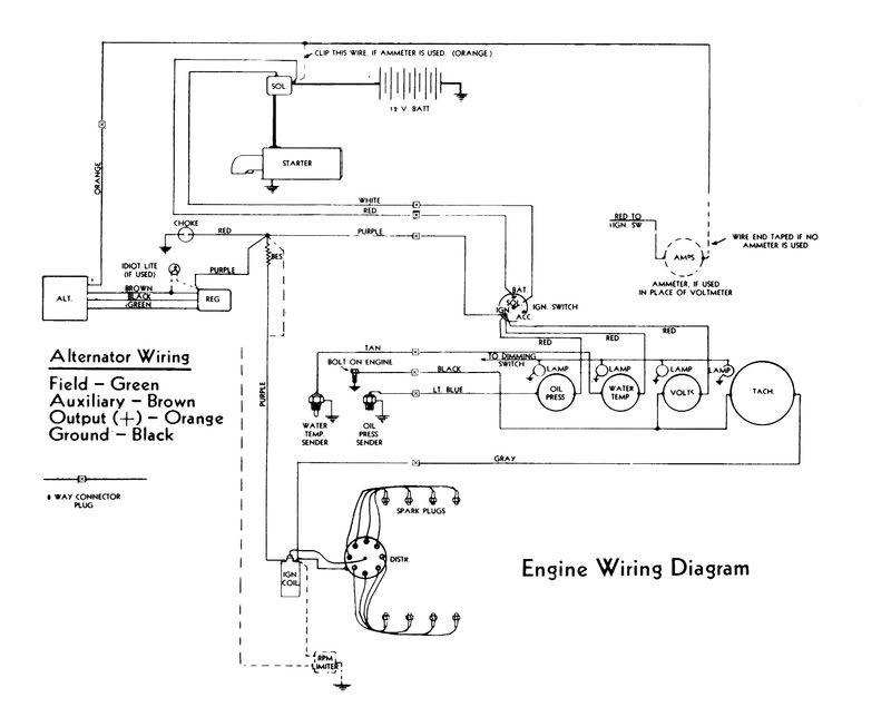
*hint: There is no breaker in that diagram. Its even more inadequate than the one in the '89 manual. |
|||
|
|||
|
Hollywood
Moderator Group

Joined: February-04-2004 Location: Twin Lakes, WI Status: Offline Points: 13510 |
Post Options
Thanks(0)
Quote Reply
Posted: February-21-2008 at 5:30pm |
||
|
Faster than somebody's in this thread...

Nah I still haven't checked the springs. It's fast enough for me, but we know it could/should be a little faster. My penis is plenty large, so making my boat faster is not a priority. |
|||
|
|||
|
79nautique
Grand Poobah
Joined: January-27-2004 Location: United States Status: Offline Points: 7872 |
Post Options
Thanks(0)
Quote Reply
Posted: February-21-2008 at 5:05pm |
||
|
Kevin we know how well you fix things, and it took how long to fix your boat? or is it still underpowered for some unknown reason you can't figure out still?
|
|||
|
|||
|
Hollywood
Moderator Group
Joined: February-04-2004 Location: Twin Lakes, WI Status: Offline Points: 13510 |
Post Options
Thanks(0)
Quote Reply
Posted: February-21-2008 at 4:56pm |
||
|
I just was "testing" you guys.
Haha, no really I just misread that post. I also like to pitch in and do my share of fueling the fire. |
|||
|
|||
|
79nautique
Grand Poobah
Joined: January-27-2004 Location: United States Status: Offline Points: 7872 |
Post Options
Thanks(0)
Quote Reply
Posted: February-21-2008 at 4:50pm |
||
nobody said anything about removing or added a curcuit breaker or fuse Kevin Tim look on page 22 of teh 302 and 351 PCM manual instead of the 89, the diagram is a lot easier to read and I've got now clue where you see the ballast coming into play. Maybe thats the problem you need a lession in reading schematics |
|||
|
|||
|
TRBenj
Grand Poobah
Joined: June-29-2005 Location: NWCT Status: Offline Points: 21107 |
Post Options
Thanks(0)
Quote Reply
Posted: February-21-2008 at 4:48pm |
||
No, he's confirming what I said. He just misused the term "protected." Only the starter and battery are on the UNprotected side. Everything else is on the protected side, that is, protected from the battery which is the greatest current source in the boat. |
|||
|
|||
|
Hollywood
Moderator Group
Joined: February-04-2004 Location: Twin Lakes, WI Status: Offline Points: 13510 |
Post Options
Thanks(0)
Quote Reply
Posted: February-21-2008 at 4:43pm |
||
So you're basically combining Tim and Chris's arguments here. Tim says dash needs to be protected from the battery by the breaker, which it is. Chris says it does not need to be protected from the alternator. So basically Tim's diagram needs the orange alt output on the other side of the 50A engine breaker. |
|||
|
|||
|
TRBenj
Grand Poobah
Joined: June-29-2005 Location: NWCT Status: Offline Points: 21107 |
Post Options
Thanks(0)
Quote Reply
Posted: February-21-2008 at 4:40pm |
||
Like I said, thanks for the help putting my diagram together. 
In the PCM manual, the electrical connections are correct, but the physical connections depicted are misleading. For example, the alternator does not connect to the ballast resistor like the diagram shows (though it is electrically equivalent). Its also difficult to tell which wires connect to which posts on the starter solenoid. The second diagram is much clearer. When youre able to see the pics, be sure to tell us if you still think the alt goes through the breaker on the way to the dash. Reference connections #22 and #23. 
|
|||
|
|||
|
Post Reply
|
Page 123> |
 Tweet
Tweet
|
| Forum Jump | Forum Permissions You cannot post new topics in this forum You cannot reply to topics in this forum You cannot delete your posts in this forum You cannot edit your posts in this forum You cannot create polls in this forum You cannot vote in polls in this forum |


 Topic Options
 skalomenos wrote: