 Boats For Sale:


Mando alt wire question |
Post Reply 
|
| Author | |
phatsat67 
Grand Poobah 
Joined: March-13-2006 Location: Indiana Status: Offline Points: 6149 |
 Post Options Post Options
") Thanks(0) Thanks(0)
 Quote Reply Quote Reply
 Topic: Mando alt wire question Topic: Mando alt wire questionPosted: September-05-2014 at 2:19pm |
|
I think it fully fields it. Those Mando Alternators put out about 14-14.5 when they are wired correctly as opposed to 12.5-13 to the older ones.
|
|
 |
|
|
Bri892001
Grand Poobah

Joined: September-27-2008 Location: Boston MA Status: Offline Points: 4947 |
Post Options
Thanks(0)
Quote Reply
Posted: September-05-2014 at 1:41pm |
|
Not sure what would happen. You said you're charging.
Wonder if not having the jumper puts it in full field output all the time. Paul, in your pic, is that original alternator, wired the original way? Any idea what your voltage reads at the battery with the engine running? |
|
|
|
|
burban89
Groupie 
Joined: January-29-2008 Location: SC Status: Offline Points: 55 |
Post Options
Thanks(0)
Quote Reply
Posted: September-05-2014 at 12:51pm |
|
So you are saying I have to have it? What happens if you dont?
|
|
|
|
|
phatsat67
Grand Poobah
Joined: March-13-2006 Location: Indiana Status: Offline Points: 6149 |
Post Options
Thanks(0)
Quote Reply
Posted: September-04-2014 at 5:15pm |
|
Yea, it's a little confusing. Our manufacturer used to supply those with the flat jumper but have since stopped. We were installing them and they weren't charging the system then we figured it out.
|
|
|
|
|
Bri892001
Grand Poobah
Joined: September-27-2008 Location: Boston MA Status: Offline Points: 4947 |
Post Options
Thanks(0)
Quote Reply
Posted: September-04-2014 at 4:24pm |
|
Thanks for the explanation Zach.
Ok, that makes sense to me now 
|
|
|
|
|
phatsat67
Grand Poobah
Joined: March-13-2006 Location: Indiana Status: Offline Points: 6149 |
Post Options
Thanks(0)
Quote Reply
Posted: September-04-2014 at 3:59pm |
|
Brian, on the right rear of the alternator the S terminal needs to be somehow connected to the large positive terminal (not to the green wire or EXC terminal. That terminal is reserved for the keyed ignition source to energize the voltage regulator. The S terminal senses actual alternator/system voltage.
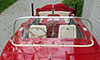
This jumper doesn't show up on the diagram because it is already jumped on the stock Mando alternators. Look at your first picture, there is a flat "wire" covered in black insulation that runs between the B and S terminals. |
|
|
|
|
Bri892001
Grand Poobah
Joined: September-27-2008 Location: Boston MA Status: Offline Points: 4947 |
Post Options
Thanks(0)
Quote Reply
Posted: September-04-2014 at 3:26pm |
|
The thing that I'm confused on with the jumper wire:
That heavy orange basically goes to a constantly live source, essentially battery positive, right? And, that green wire, goes to ignition key switched purple, right? If both of the above are true, doesn't running a jumper from the orange to the green essentially energize the ignition circuit constantly? I'm not saying I know the whole story by any means, just curious to hear how the jumper thing works. I'm going off of this diagram: 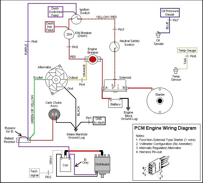
|
|
|
|
|
phatsat67
Grand Poobah
Joined: March-13-2006 Location: Indiana Status: Offline Points: 6149 |
Post Options
Thanks(0)
Quote Reply
Posted: September-04-2014 at 2:59pm |
|
Gotta watch some of those too. They don't have that solid jumper from the large positive to the S signal terminal so a jumper is needed there.
We get ours from a local warehouse (that is USCGA) but much cheaper than pcm but they require the additional jumper wire. |
|
|
|
|
burban89
Groupie
Joined: January-29-2008 Location: SC Status: Offline Points: 55 |
Post Options
Thanks(0)
Quote Reply
Posted: September-04-2014 at 11:34am |
|
appreciate the pic, the other post helped me get it right. I left the jumper off. It is definitely charging better with the new alt.
|
|
|
|
|
gun-driver
Grand Poobah
Joined: July-18-2008 Location: Pittsburgh, Pa Status: Offline Points: 4112 |
Post Options
Thanks(0)
Quote Reply
Posted: September-04-2014 at 11:20am |
|
Here's a pic of my '95 GT-40 wiring

|
|
|
|
|
Bri892001
Grand Poobah
Joined: September-27-2008 Location: Boston MA Status: Offline Points: 4947 |
Post Options
Thanks(0)
Quote Reply
Posted: August-28-2014 at 8:45pm |
|
Not sure on the jumper.
If you jump the sense to hot, that sensor will always be on... that could potentially be putting a draw on your battery when the motor is not running. The jumper is probably a work around for boats/engines not originally wired for the sensor. |
|
|
|
|
burban89
Groupie
Joined: January-29-2008 Location: SC Status: Offline Points: 55 |
Post Options
Thanks(0)
Quote Reply
Posted: August-28-2014 at 7:54pm |
|
Yeah the the one that is circled purple is actually a green wire that runs back to a purple wire. The gound has a purple stripe on it and that is what confused me.
What is the sensor jumper wire? A lot of diagrams show a jumper from the sense to hot? Pretty sure my old one didn't have one. I just hooked it all back up and have 100% power to electronics. Hope to make a lake test tonight. |
|
|
|
|
Bri892001
Grand Poobah
Joined: September-27-2008 Location: Boston MA Status: Offline Points: 4947 |
Post Options
Thanks(0)
Quote Reply
Posted: August-28-2014 at 11:52am |
|
If this is the same alternator you have (I think it should be), this pic should help with the wiring:

|
|
|
|
|
burban89
Groupie
Joined: January-29-2008 Location: SC Status: Offline Points: 55 |
Post Options
Thanks(0)
Quote Reply
Posted: August-28-2014 at 9:24am |
|
OEM style replacement. I am going to go back and make sure I bolted everything down today. Hopefully get a lake test as I havent had a lot of time.
|
|
|
|
|
Bri892001
Grand Poobah
Joined: September-27-2008 Location: Boston MA Status: Offline Points: 4947 |
Post Options
Thanks(0)
Quote Reply
Posted: August-27-2014 at 3:15pm |
Ha, I guess I glossed over this part. That would definitely explain your no crank condition. Is the alternator you're working with an OEM or OEM style replacement, or is part of a retrofit/upgrade kit. |
|
|
|
|
burban89
Groupie
Joined: January-29-2008 Location: SC Status: Offline Points: 55 |
Post Options
Thanks(0)
Quote Reply
Posted: August-27-2014 at 2:16pm |
|
sorry due to my other engine post i didnt think about posting that info here.
1995 supersport pro boss gt 40 |
|
|
|
|
Bri892001
Grand Poobah
Joined: September-27-2008 Location: Boston MA Status: Offline Points: 4947 |
Post Options
Thanks(0)
Quote Reply
Posted: August-26-2014 at 5:14pm |
|
It would help us if you mentioned what year your boat is. Some aspects of wiring have changed along the way. Also, mention what marinization (PCM etc.) because that affects things as well.
|
|
|
|
|
TX Foilhead
Grand Poobah

Joined: February-01-2009 Location: Kingsland TX Status: Offline Points: 2076 |
Post Options
Thanks(0)
Quote Reply
Posted: August-26-2014 at 4:21pm |
|
Solenoid (starter relay?) needs a ground, I've had problems with replacements not getting a good ground through the case so I built a short 2ga jumper that I connect between a bolt and the head.
The jumper with the sense wire is not ideal, but will work. |
|
|
|
|
burban89
Groupie
Joined: January-29-2008 Location: SC Status: Offline Points: 55 |
Post Options
Thanks(0)
Quote Reply
Posted: August-26-2014 at 1:03pm |
|
I have been thinking about this all day at work, I do not think we bolted the solenoid back to the motor for testing, does that ground to the engine? Maybe that is why it would not do anything?
|
|
|
|
|
burban89
Groupie
Joined: January-29-2008 Location: SC Status: Offline Points: 55 |
Post Options
Thanks(0)
Quote Reply
Posted: August-26-2014 at 8:47am |
|
Ok so after a lot of searching I came across a good read that lead me into the right direction. Now my question is do I have to have the jumper wire? I am 99.999% sure my old one did not. Could it have been internal?
So now I have power back to everything but when I turn the key I get nothing. The ignition button powers all the gauges and the volts look right. It may be Thursday before I can spend more time in boat. Could that missing jumper wire cause me to get nothing when i turn the key? Could I have fried the coil or something with the alt ground hooked to exciter? The heavy Orange wire connects to the "B" terminal which is the alternator's output terminal. The Green wire needs a ring terminal and connects to the "EXC" terminal which is the Field Excitation terminal (goes to +12V when the ignition is ON). This is despite the color coding you may have seen in some Mando diagrams like the one attached to this post. The green wire eventually connects to the Purple ignition wire, somewhere back in the harness or terminal block. The Black wire is a redundant/backup connection to the engine block (ground) and should be connected to the "E" (for "Earth") terminal, which is the alternator's frame. There should be a jumper link between the "B" terminal and the "S" terminal which is the voltage sense terminal for the alternator's internal regulator (see the photo in the previous post). If that jumper is not there, you need to make one. I'd use a #12 AWG wire. The "P" terminal is an AC output to a tachometer (would be used on a Diesel installation - unless it has a tach sender on the crank). Leave this terminal unconnected. The "L2" terminal is for connection to an "Idiot Light" on the instrument cluster. It would light up if the alternator were not charging, like on a car. This terminal is left unconnected since the boat has an ammeter. I am not sure if it is functional on the Mando alternator but it may be. Since you've now had the 1000 words, here are a couple of pictures also: 1 - The terminal pin-out for a Mando (ignore the Black or Purple wire reference to the "EXC" terminal). 2 - A wiring diagram for a PCM engine showing the three wires connected to the alternator. The Black ground wire is shown in a confusing position on the alternator, in the sketch, but does indicate it connects to the engine block. http://www.fishtheclassic.net/forums/archive/index.php/t-17942.html |
|
|
|
|
burban89
Groupie
Joined: January-29-2008 Location: SC Status: Offline Points: 55 |
Post Options
Thanks(0)
Quote Reply
Posted: August-25-2014 at 8:45pm |
|
Ok so I have seen diagrams but am still arguing with my friend on wiring.
Orange is main power Purple strip is exciter Leaves the green to be ground? I've confused myself. I don't have a black ground. Orange dark wire with purple stripe and green. Green is completed melted now. Anyone able to tell me what's what? |
|
|
|
|
Post Reply
|
|
 Tweet
Tweet
|
| Forum Jump | Forum Permissions You cannot post new topics in this forum You cannot reply to topics in this forum You cannot delete your posts in this forum You cannot edit your posts in this forum You cannot create polls in this forum You cannot vote in polls in this forum |


 Topic Options
 burban89 wrote: