 Boats For Sale:


Shaft Coupler gap |
Post Reply 
|
| Author | ||
NeilMcG 
Senior Member 
Joined: September-20-2021 Location: Pittsburgh, PA Status: Offline Points: 230 |
 Post Options Post Options
") Thanks(0) Thanks(0)
 Quote Reply Quote Reply
 Topic: Shaft Coupler gap Topic: Shaft Coupler gapPosted: July-16-2024 at 10:27pm |
|
|
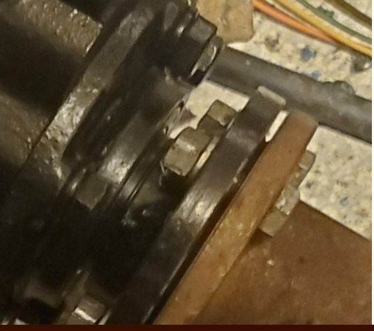
While trying to mate the prop shaft to the trans I realized that the two surfaces could not be flush mounted. After reviewing photos from before the restore I came across this one showing how it was originally. Is this something to be worried about? It's a tad more than .003 so I don't know what to make of this.
Thanks
 |
||
 |
||
|
67 ski nat
Platinum Member 
Joined: July-19-2018 Location: Santa rosa Status: Offline Points: 1194 |
Post Options
Thanks(0)
Quote Reply
Posted: July-17-2024 at 9:47am |
|
|
Sure seems wrong
Can you fit together by hand, will they mate at all. Is there crap , rust needs cleaning |
||
|
||
|
MourningWood
Gold Member
Joined: June-13-2014 Location: NorCal Status: Offline Points: 918 |
Post Options
Thanks(0)
Quote Reply
Posted: July-17-2024 at 11:45am |
|
|
So there is an 'indexing ring' cast into the mating surface of the shaft flange, and a corresponding register in the trans flange. They fit together. Or they should.
Try it without the bolts...
|
||
|
1964 Dunphy X-55 "One 'N Dun"
'I measured twice, cut three times, and it's still too short!" |
||
|
||
|
MrMcD
Grand Poobah 
Joined: January-28-2014 Location: Folsom, CA Status: Offline Points: 3764 |
Post Options
Thanks(0)
Quote Reply
Posted: July-17-2024 at 12:45pm |
|
|
As already mentioned both halfs need to be clean. When you bring the shaft forward they should mate up flush, no bolts in place. When they are flush you measure the gap at all points of the clock. You may find you have .008 at the 6 pm position while it is tight at the 12 am position or any combination.
Next you adjust your engine mounts till you get the mating surfaces to meet with no gap. .003 is the max allowed. I was happy to get mine down to .0015 with patient adjusting. If you can't get the engine aligned to the shaft you might need to repair/adjust the strut. Spin your prop shaft with it about 1/2" away from the coupler. See where it spins with the least resistance. You will need to support the shaft at the front, just the weight of the shaft will cause some drag in the strut. The shaft will have a Happy Place, where it spins with the least resistance. Hopefully this spot is pointed directly at your coupling. If it is off you find out why and adjust. There is a lot of information on this forum to direct you to a good alignment.
|
||
|
||
|
NeilMcG
Senior Member
Joined: September-20-2021 Location: Pittsburgh, PA Status: Offline Points: 230 |
Post Options
Thanks(0)
Quote Reply
Posted: July-17-2024 at 10:08pm |
|
All of the rust is gone and both mating surfaces are clean. There is a circular ring on the shaft coupler side but nothing on the trans side to mate into it.
|
||
|
||
|
NeilMcG
Senior Member
Joined: September-20-2021 Location: Pittsburgh, PA Status: Offline Points: 230 |
Post Options
Thanks(0)
Quote Reply
Posted: July-17-2024 at 10:09pm |
|
Yep, there is an indexing ring, but no female counterpart on the trans side,
|
||
|
||
|
NeilMcG
Senior Member
Joined: September-20-2021 Location: Pittsburgh, PA Status: Offline Points: 230 |
Post Options
Thanks(0)
Quote Reply
Posted: July-17-2024 at 10:17pm |
|
I really can't get on the alignment aspect once I get the flange situation understood. The pic shown is how it was for years...and it worked just fine. I just can't seem to figure out why there is a gap (it's not from any debris.) It's almost as if there is an intentional gap factored into this design. This is a standard Velvet Drive 1017
|
||
|
||
|
NeilMcG
Senior Member
Joined: September-20-2021 Location: Pittsburgh, PA Status: Offline Points: 230 |
Post Options
Thanks(0)
Quote Reply
Posted: July-17-2024 at 10:38pm |
|
No. The two flanges cannot mate flush The pic below is an old one...all of the rust has been removed. It's the center indexing portion that has me stumped because there is no cavity on the transmission side for it to mate into. Perhaps this is simply the way it was designed with the clearances being measured between the trans flange and that inner race (for the lack of a better term.) 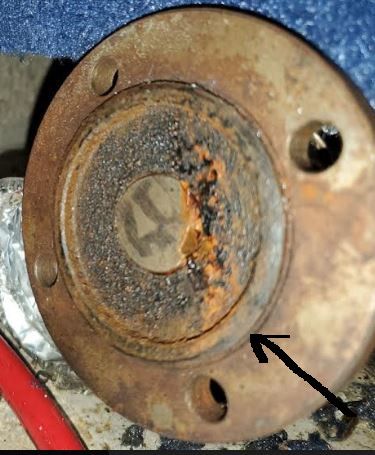 |
||
|
||
|
MrMcD
Grand Poobah
Joined: January-28-2014 Location: Folsom, CA Status: Offline Points: 3764 |
Post Options
Thanks(0)
Quote Reply
Posted: July-18-2024 at 2:35am |
|
|
If you can't bring the prop shaft up to the transmission coupler and mate them something is very wrong. Even if the alignment is quite a bit out you can move the shaft into position and mate them with a little encouragement by hand.
If yours won't mate I suspect some previous owner took a shortcut and assembled your shaft with parts that do not match. I would have to look but I had a 1" factory Nautique coupler that only had 100 hours on it when I replaced it with an ARE shaft and coupler. I believe the factory unit is brass, yours looks like cast iron or steel.
|
||
|
||
|
KENO
Grand Poobah
Joined: June-06-2004 Location: United States Status: Offline Points: 11155 |
Post Options
Thanks(0)
Quote Reply
Posted: July-18-2024 at 8:11am |
|
|
Since you've apparently remastered the fine art of posting pictures around here, how about a picture of the transmission coupler showing the flange and the big retaining nut ?

|
||
|
||
|
NeilMcG
Senior Member
Joined: September-20-2021 Location: Pittsburgh, PA Status: Offline Points: 230 |
Post Options
Thanks(0)
Quote Reply
Posted: July-18-2024 at 11:54am |
|
Oh my...stand by. In my haste I may have missed something BIG on the trans side. You really are psychic. I wondered if you'd comment about my newly acquired skill of posting. |
||
|
||
|
KENO
Grand Poobah
Joined: June-06-2004 Location: United States Status: Offline Points: 11155 |
Post Options
Thanks(0)
Quote Reply
Posted: July-18-2024 at 12:46pm |
|
|
Here's what the transmission flange should look like. The end of the output shaft with the blue arrow pointing to it sticks out about 1/16 of an inch beyond the flange face and there's enough of a dish in the shaft coupler that the 2 faces will touch without the output shaft touching the end of the driveshaft in the coupler. Picture coming soon of an original shaft coupling from a 76 SN Ignore the wheels 
|
||
|
||
|
KENO
Grand Poobah
Joined: June-06-2004 Location: United States Status: Offline Points: 11155 |
Post Options
Thanks(0)
Quote Reply
Posted: July-18-2024 at 1:05pm |
|
|
A little while later....here's a picture of a coupling from a 76 SN. It's made of steel.
The dished area in the middle is about 5/16 of an inch below what's being called the indexing ring and there's plenty of clearance between the output shaft and the driveshaft ends when the 2 mating faces are touching with no gap.(not a long ways apart like yours) |
||
|
||
|
MrMcD
Grand Poobah
Joined: January-28-2014 Location: Folsom, CA Status: Offline Points: 3764 |
Post Options
Thanks(0)
Quote Reply
Posted: July-18-2024 at 5:33pm |
|
|
I have my 1995 coupler in my hand, it is identical to the second one Ken has posted.
|
||
|
||
|
MourningWood
Gold Member
Joined: June-13-2014 Location: NorCal Status: Offline Points: 918 |
Post Options
Thanks(0)
Quote Reply
Posted: July-18-2024 at 7:38pm |
|
Vegas oddsmakers are favoring oversize 'Big Nut'.......
|
||
|
1964 Dunphy X-55 "One 'N Dun"
'I measured twice, cut three times, and it's still too short!" |
||
|
||
|
wayoutthere
Senior Member
Joined: February-28-2020 Location: Florida Status: Offline Points: 492 |
Post Options
Thanks(0)
Quote Reply
Posted: July-19-2024 at 11:09am |
|
|
Pull the shaft back far as it will go and post a picture of both the transmission and shaft flanges please. If possibe take some measurements or be prepared to.
|
||
|
||
|
Post Reply
|
|
 Tweet
Tweet
|
| Forum Jump | Forum Permissions You cannot post new topics in this forum You cannot reply to topics in this forum You cannot delete your posts in this forum You cannot edit your posts in this forum You cannot create polls in this forum You cannot vote in polls in this forum |


 Topic Options
 67 ski nat wrote: