Help: Ammeter to Volt gauge switch out
Printed From: CorrectCraftFan.com
Category: Repairs and Maintenance
Forum Name: Boat Maintenance
Forum Discription: Discuss maintenance of your Correct Craft
URL: http://www.CorrectCraftFan.com/forum/forum_posts.asp?TID=11868
Printed Date: September-29-2024 at 1:25pm
Topic: Help: Ammeter to Volt gauge switch out
Posted By: kman
Subject: Help: Ammeter to Volt gauge switch out
Date Posted: September-06-2008 at 4:25am
|
'76 Southwind. Took OEM Teleflex ammeter out. It had about four large orange wires connected to the S terminal; three to the ground; one to the I terminal and one to the L terminal. I put in a new teleflex volt gauge: connected the power back to the I term. and the grounds back to the ground, and the blue L wire back to the L term. The voltmeter stays on like it is wired straight to the batt. So, I removed the power and tried pulling power from the ignition but nothing happened. Question: I'm unclear about what the wiring diagram says to do with the orange wires since I don't use them on the volt gauge; just cap them off or disconnect them totally from the boat? I want to get the power from something that turns on with the ignition right? Also, not sure if this even happened, but is it possible to short out the alternator just by messing with wiring? I tried connecting the wiring back they way it came off and I can't get the igintion to fire. All dash fuses are good. Or could it be possible to fry the ignition switch? ------------- Kirk 1976 Southwind 20 Eagle Mountain Lake Fort Worth |
Replies:
Posted By: 8122pbrainard
Date Posted: September-06-2008 at 11:44am

Kirk, is this the wiring diagram you are using? It shows both the amp and volt meter wiring. All the orange that you removed from the amp, get connected together ether on a separate terminal or bolted together and insulated. ------------- /diaries/details.asp?ID=1622" rel="nofollow - 54 Atom /diaries/details.asp?ID=2179" rel="nofollow - 77 Tique 64 X55 Dunphy Keep it original, Pete < |
Posted By: kman
Date Posted: September-06-2008 at 1:10pm
|
yes. So I will just cap them off. New question. I work on my boat when it is on the hydrohoist lift. Could that affect the ground. Once when I had the radio on and I lowered the boat, the radio went out right when the boat touched the water. Should I put the boat in the water to ensure it is grounded? ------------- Kirk 1976 Southwind 20 Eagle Mountain Lake Fort Worth |
Posted By: 8122pbrainard
Date Posted: September-06-2008 at 2:04pm
|
Kirk, No, putting the boat in the water or having it out won't have a effect on the ground. Think about it, if it was a problem, we wouldn't have airplanes!! Check all your ground connections up to and including the dash. I ended up removing every connection on my 77 in the entire boat picking up like 1.5 volts to the dash due to resistance caused by corrosion. Also replaced all the .250" quick connect spade "Sta-cons" because the brass on the originals were hard/brittle/ cracked causing poor connections. ------------- /diaries/details.asp?ID=1622" rel="nofollow - 54 Atom /diaries/details.asp?ID=2179" rel="nofollow - 77 Tique 64 X55 Dunphy Keep it original, Pete < |
Posted By: kman
Date Posted: September-06-2008 at 2:16pm
|
will do ------------- Kirk 1976 Southwind 20 Eagle Mountain Lake Fort Worth |
Posted By: 8122pbrainard
Date Posted: September-06-2008 at 4:27pm
|
Kirk, I meant to say clean up/check all your connection and not just the grounds. Also, open up any of the rubber multipin plugs that may be in the wiring harness around the engine. I found one that was so corroded that I'm surprised it worked! A Scotch brite pad works for the clean up and using dielectric grease when yo assembly will keep the corrosion from coming back. ------------- /diaries/details.asp?ID=1622" rel="nofollow - 54 Atom /diaries/details.asp?ID=2179" rel="nofollow - 77 Tique 64 X55 Dunphy Keep it original, Pete < |
Posted By: kman
Date Posted: September-07-2008 at 3:42am
|
Well, I tried to wire it up again and then a airplane mechanic buddy of mine showed up and looked at everything. He noticed where the manual talks about the orange wire coming from the battery to the wiring harness and something about a shunt. Over my head, but he said he could help. Looks like we have to redo some wiring at the wiring harness. Does that sound right? My friend said he could handle it easily. In fact he said he could trace all the wires on the back of the dash and draw up a new wiring diagram for my boat. ------------- Kirk 1976 Southwind 20 Eagle Mountain Lake Fort Worth |
Posted By: 8122pbrainard
Date Posted: September-07-2008 at 9:57am
|
Kirk, Glad you found someone to help out. To tell you the truth, I did mean to post the larger diagram after your "put the boat in the water for grounding" question. You scared me on that one or at least it did tell me that you are electrically challenged!!! Here's the same diagram that I had in my photo bucket that comes out larger when posted. I thought it may help even though you now have you friend giving you a hand.
The easy way is to connect all the orange and the red wire to the "bat" terminal on the ignition switch that were on the back of the amp meter. This does the same as connecting the orange wire directly to the solenoid where it says "clip this wire if ampmeter is used". The only difference is it does add 15' or so of wire to the circuit to charge the battery. You will see as slight voltage drop to the battery due to this extra wire length but nothing significant to make a difference. The red and orange wires are normally the same gauge so unless you have added a higher amp alternator (requiring larger gauge wire) it really is the easy way to do it. The volt meter then gets wired up just as shown: any black ground and to the "ign." term red wires to all the gauges. 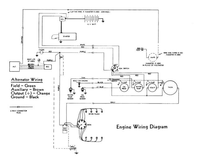
A shunt in it's simplest form is a jumper. He's probably referring to the "clip this wire" to the solenoid. ------------- /diaries/details.asp?ID=1622" rel="nofollow - 54 Atom /diaries/details.asp?ID=2179" rel="nofollow - 77 Tique 64 X55 Dunphy Keep it original, Pete < |
Posted By: kman
Date Posted: September-15-2008 at 4:40pm
Pete - I couldn't wait on my friend and your last advice made sense so I went back to put the volt gauge in yesterday and it worked. I took the five orange wires off the S terminal and the one red wire off the I term of the ammeter and connected them to the BAT term of the ignition. I then put the ground wires and blue light wire back the new volt gauge and ran an ignition wire from the speedo to the I term on the volt gauge. So everything works. QUESTION 1: The orange wires are HUGE. Almost a 1/4 the size of the Bat cable and I think I recall reading something about using a different gauge wire when switching from ammeter to volt gauge. Is it OK to run those five huge orange wires to the BAT term on the ignition like you said or is something going to burn up? I ran the boat after I was finished and couldn't find any hot wires, but something still doesn't seem right. QUESTION 2: If the orange wires are going to the bat term, are they even needed at all. It looks like they are creating a loop back to the battery. Are they just for the ammeter or do they help other gauges? Does the wiring look this messy on all old CC's. This boat has only had one gauge change since it's birth. See the pic.


 ------------- Kirk 1976 Southwind 20 Eagle Mountain Lake Fort Worth |
Posted By: nuttyskier2002
Date Posted: September-15-2008 at 6:12pm
|
Kman, the ammeter was wired in series between the battery and the alternator. Also the ignition switch is fed from this circuit on the "I" side of the ammeter. You can clean up your wiring a bit if you run a large (10 gage) wire from the alternator straight to the Batt side of you starter solenoid. Then feed to "Batt" side of the ignition switch with another large gage wire from the "Batt" side of the solenoid. The remainder of these large orange wires are the sources of your accessories. You can leave them disconnected until you find out which ones are needed. Once everyhting is working, pull (or cap off) all the wires that are not needed. I can talk you through this if you want and give you more details. Give me a call!
480-365-8989 ----- Brian ------------- 95 Malibu Echelon w/Mercruiser 350 Magnum Skier Former boats: 88 Ski Centurion Tru Trac II 59 Chris Craft Capri (woody) |
Posted By: kman
Date Posted: September-15-2008 at 6:52pm
|
Thanks for the offer. Sounds like 10ga wire and a 6 pack can get her done. I'll try to call you later today to make sure I get it. ------------- Kirk 1976 Southwind 20 Eagle Mountain Lake Fort Worth |
Posted By: 8122pbrainard
Date Posted: September-16-2008 at 10:15am
|
Kirk,
What you have found under the dash is the normal OEM rats nest!!! Don't worry about the wire gauge. You haven't added any extra loads (amps) that would require it. Larger ga. wire is needed when higher output alternators are used with extra the extra loads. I'm Trying to picture what you did with the orange (they are red - the only orange will be the old feed to the old amp meter) wires. These red wires are they the ones to all the gauges? If so, They should be switched off the IGN. terminal on the ignition swith. Going to the BAT terminal will keep them powered up all the time. Accessories (bilge pump, blower, etc.) can go to the BAT term because they are switched separately. At least you haven't gotten to the smoke test failure point!! I remember way back in high school electronics that the end of the year would come. Or teacher would power up everyones projects. If they smoked, you got a "F" on the project!! BTW, I had a smoker!! Can't remember what I had built!! ------------- /diaries/details.asp?ID=1622" rel="nofollow - 54 Atom /diaries/details.asp?ID=2179" rel="nofollow - 77 Tique 64 X55 Dunphy Keep it original, Pete < |