1991 Sport Nautique Open Bow Stringer
Printed From: CorrectCraftFan.com
Category: Repairs and Maintenance
Forum Name: Boat Maintenance
Forum Discription: Discuss maintenance of your Correct Craft
URL: http://www.CorrectCraftFan.com/forum/forum_posts.asp?TID=49484
Printed Date: January-16-2025 at 12:14am
Topic: 1991 Sport Nautique Open Bow Stringer
Posted By: Ian H
Subject: 1991 Sport Nautique Open Bow Stringer
Date Posted: December-14-2020 at 10:46pm
|
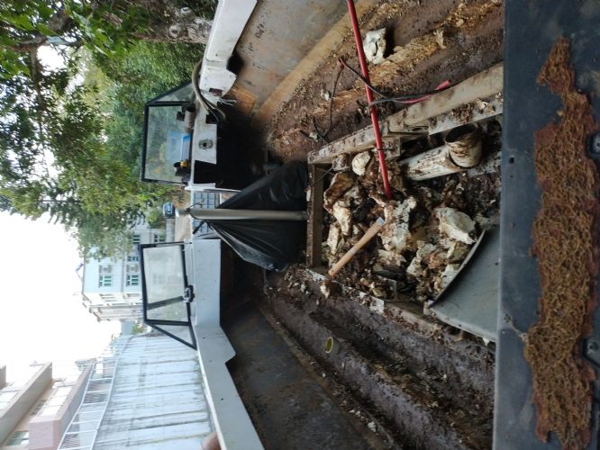
I have rescued a 1991 Sport Nautique with an Open Bow from the Jungle in Hong Kong. The floor is spongy so I expect a lot of rot and I have been studying hard for a full stringer replacement. But I cannot find an example of how to deal with the floor of the open bow. What's the method for open bow stringer replacement? Photos to show I am a true dreamer   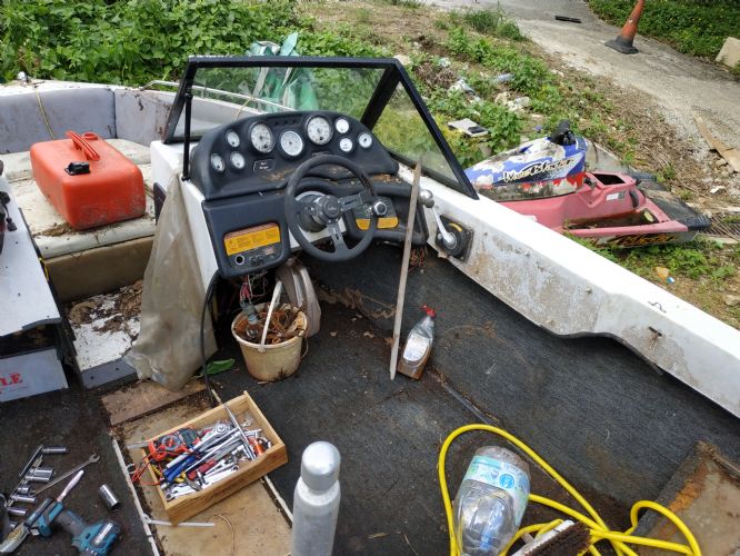 |
Replies:
Posted By: SNobsessed
Date Posted: December-15-2020 at 7:26am
|
That looks like quite a project just to move it. Some guys remove the whole top section (called the cap) so they can access the entire hull length. I hope you have a shop, this will take a few months to do. ------------- “Beer is proof that God loves us and wants us to be happy.” Ben Franklin |
Posted By: fanofccfan
Date Posted: December-15-2020 at 8:22am
|
This one will be a great follow. Looking forward to watching the progress. ------------- 2004 196 LE Ski 1969 Marauder 19 1978 Ski |
Posted By: sport1999
Date Posted: December-15-2020 at 1:25pm
|
Funny. There was a 1990 Sport Nautique with a trailer in similar condition near me. It was priced at a $100.00. Not sure about boat prices over there, but I wouldn't call that free. Good luck. There is a nice stringer replacement for a Sport Nautique on this forum somewhere.
Pictures are gone, but here is one with information. http://https://www.correctcraftfan.com/forum/forum_posts.asp?TID=37914&PN=1&title=1992-sport-floor-replacement" rel="nofollow - http://https://www.correctcraftfan.com/forum/forum_posts.asp?TID=37914&PN=1&title=1992-sport-floor-replacement
|
Posted By: MechGaT
Date Posted: December-15-2020 at 9:35pm
|
That was my ‘92. I didn’t split the boat and take off the cap. I saw elsewhere that basically it involves removing the rubrail and that is where the two pieces join. The stringers don’t go all the way under the front seating. They stop just in front of the driver and observer seats. If the floor in the bow is soft then the only way to fix it is split it, as you have said. Replacing the stringers was enough work for me. I will be glad to pass along whatever knowledge I can. ------------- '92 Sport Nautique |
Posted By: Ian H
Date Posted: December-18-2020 at 12:06am
|
I am all prepped for cutting into the floor and having a look at what is there, but since the bolts holding the engine frame just rotate I think the stringers must be rotten so I don t expect anything but a full floor and stringer removal. So I am getting ready for a marathon cutting session tapped into a Tyvak suit with respirator. I made carboard templates of the floor since i guess making the right shape later will be a headache with not floor in place and marked datums on of the hull so I should be able to get the engine mount positions correct again I should know shortly if I can reach the ends of the stringers or if I need to cut into the cap of the open bow. Did you replace the whole stringer without spitting the cap of open bow? Do you have any photos of what your stringer replacement was like? If I need to get in to the bow I am thinning of cutting out the floor of the open bow by cutting the red line and bolting boards over the cut line before I cut so I can bolt the boards on the back when I reassemble to get the location and then glass them in. I am sure I am going to need some advice once I get inside , I will post some photos of the itchy carnage.  Regards Ian 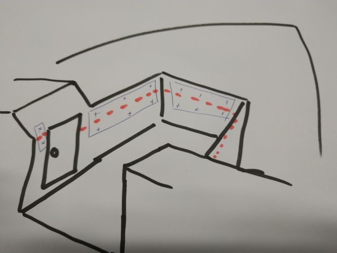 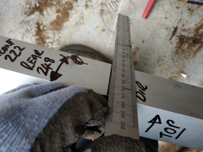 |
Posted By: MechGaT
Date Posted: December-19-2020 at 10:43am
|
I updated my thread with some pictures of the process I went through. One of the first posts includes a picture of the end of the stringers. They end right at the storage compartments in the foot area of the driver and passenger. I would not cut at the red line you have shown. Splitting the cap involves removing the rubrail, removing the rivets or whatever holds the cap to the hull, then cutting along that line. There is foam inside under the gunwales that will probably be in the way a bit. Look under there and see what you have. The 1999 Longhorn thread has/had some pictures of what a cap and hull separated looks like. I just found on page 13 where it still has a picture of just the hull without a cap. Also, I was very concerned about locating everything, but the pylon, engine cradle, and lip around the edge of the floor that I kept as long as I could, helped to locate everything. Definitely take measurements, but don't worry if you miss a measurement or two. If you remove the pylon mount, then all bets are off. ------------- '92 Sport Nautique |
Posted By: Ian H
Date Posted: December-19-2020 at 8:36pm
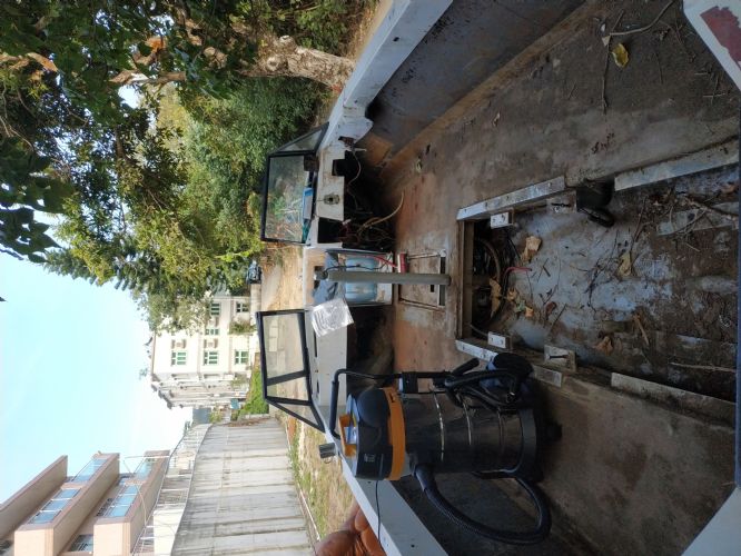   I I cannot find or search the 1992 sport floor replacement post. So still not able to see your pictures. Can you send me a link.and I can try am work out what I am doing wrong.
Thanks for the advice on the cap. I got into the floor yesterday and can now see the stringers finish within reach. So I am not committed on the cap yet. I hope I will be able to check out the posts you sent and decide what to do as the next step I still have plenty to do in the back. I think it may be structurally ok but looks like there is an old termite next made of mud forward in the foam on the Port side which I will want to clean out so may need to open to access. The cradle is still in place and bolted to the pylon. i will take a few more measurements and make some more marks to be sure I know where it goes when I come to set up the stringers . The stringers are just empty shells all the wood is rotted away or been eaten by insects so I have no remnants of wood only the stringer boxes to try to make a pattern. After measuring today's job is cut out all the stringers and smooth off to the hull. Thanks for the help  |
Posted By: MechGaT
Date Posted: December-19-2020 at 10:25pm
|
https://www.correctcraftfan.com/forum/forum_posts.asp?TID=37914&title=1992-sport-floor-replacement" rel="nofollow - 1992 Sport thread https://www.correctcraftfan.com/forum/forum_posts.asp?TID=48209&PN=10&title=1999-longhorn-nautique-restoration-thread" rel="nofollow - 1999 Longhorn Nautique pg 10 You are making some good progress. Keep it up. ------------- '92 Sport Nautique |
Posted By: Ian H
Date Posted: December-26-2020 at 7:31pm
|
The fiberglass stronger sides of the stringers inside the bilge re good and strong. should I try to leave them in and put my new stringers in along side them ... or is fitting in and filling in the void to tricky? in the bilge the thickness is about 3 to 4 mm so feels like it is pretty strong even without the stringer. not sure what is better clean start or add onto the existing strength.... |
Posted By: 8122pbrainard
Date Posted: December-26-2020 at 7:37pm
|
This has come up before and the general concensus you are better off starting over with a clean bare hull. If you try to use the existing glass, the big problem is bonding the new stringer to the old glass. ------------- /diaries/details.asp?ID=1622" rel="nofollow - 54 Atom /diaries/details.asp?ID=2179" rel="nofollow - 77 Tique 64 X55 Dunphy Keep it original, Pete < |
Posted By: Ian H
Date Posted: December-26-2020 at 9:41pm
|
thanks , i thinks getting the fit and the bond under setting time pressure would be problematic. So out they come! |
Posted By: Ian H
Date Posted: December-27-2020 at 10:41am
|
OK Stringers are out and Test with belt sander does a good job to clear up the remnants from the cutting. I guess the trick is to go down to material to get a good key for the glassing in of the new stringers. and not digging down to the hull itself. I now need time to do all the stringers. I now turn to the puzzle of the front end, under the bow floor was plywood which is now just mush and the ski locker glass fixing it to hull has let go of the bond to the locker. The locker is filled with a home made basalt tank and so is the open bow they were glassed in, in place but are separate tanks with fill and empty pumps and an inlet through the hull just behind the pylon. Picture shows the ski locker tank on its way out , the bow foot well tank fills the full space level with the seats the front of it can be seen in the first bow shots when the boat was first recovered. ( I am new to this kind of boat so I ave no idea if ballast here will be good thing.) I have studied Youtube and there is no way for me to split cap this from this boat I am outside and need to get this finished before March when the furnace sun and 90% humidity + a lot of rain will make life very difficult. But I want to fix the floor properly the foot well of the open bow is filled with the second ballast tank so I am thinking again of removing just the foot well to get access to the floor and bolting then glassing through the lockers to put it back together after fixing the floor under the foot well. I guess under the bow floor is going to be another big mush of waterlogged foam and rotten wood now when I stand on the bow floor the screens move. So need to do something to get a solid floor under the bow floor. 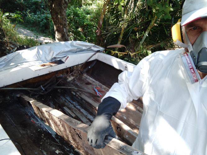 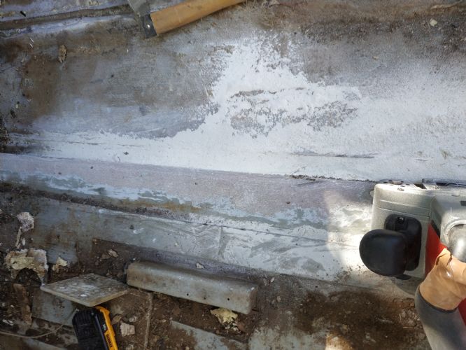   |
Posted By: Ian H
Date Posted: December-28-2020 at 10:26am
|
I have had a bit more time digging round the front end and managed to get all the rotting carpet out to get a better look, most importantly I managed to get the carpet put under the floor of the cap on top of the ski locker. Now I have a gap to work with to join the floor further forward bu the vent pipes. I still have the problem of the ballast tank in the ski locker. I cannot get it out until I get the pylon out which of course is corroded solid in cup. by the looks of it my pylon is going to get a bit shorter as I expect no amount of hammer violence is going to get it out and it will get cut it of flush with the cup and I can cut out the remnants of the corroded part from the inside. Cup already wobbles in the hull so do not want to bash it too much. Once I can see inside the ski locker I hope i can think of a good plan. It would help to know to rejoin with the ski locker any photo or a description would be helpful. ski locker I am thinking to make the whole floor with resin soaked marine ply rather than foam and skin on top. Im thinking what to do with the + 18mm of plywood thickness taking it off the stringers or making the floor a bit higher. I am now searching for my resin and mat supply. I have no idea how much of this I will need, anyone got an idea of what they used would be a great help. > tank needs to come past the pylon  how long is that locker? how long is that locker?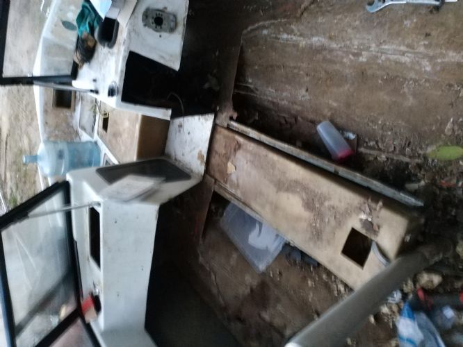 So happy with this piece of scabby carpet out from under the front floor 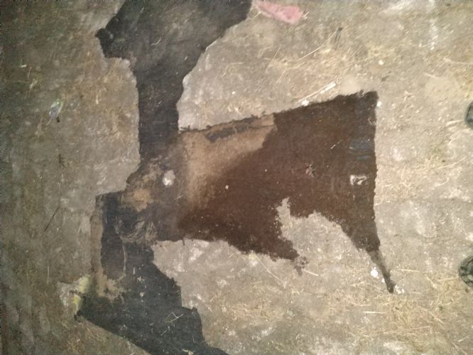 bow ballast tank  tank out  three ports bilge ballast out and ballast air vent ... Normal?  Great weather in Hong Kong  for now.... for now....  |
Posted By: MechGaT
Date Posted: December-31-2020 at 2:32pm
Here is the inside of the ski locker. Does this help?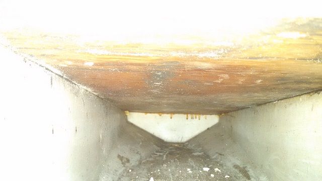 ------------- '92 Sport Nautique |
Posted By: Ian H
Date Posted: December-31-2020 at 7:16pm
|
Thanks, Yes it makes it clear that the tank must come out so i can see the condition of the top and if its still attached. pylon is stuck fast in the cup with corrosion i will try a few more things but looks like the cup will have to be cut off the hull and re glassed in  I have my stingers now from a scrap yard close to the boarder with china and floor I have 15mm birch marine ply. I have a couple of things i cannot work out from your thread. I guess many of the pictures are not there ( sorry if they are obvious I am feeling very Newbie > Did you cut down the height of the stringers by the thickness of the floor and put it on top? What ply did you use? > If you used a plywood floor what is all the foam shaping? I was planning to put in the ply with some holes to put in the foam and just cut off the extra and smooth the holes. I think I am missing something fundamental.. > What did you do to join the old floor at the front under the dashboard and the new floor > Why is there a need to use faring compound ? I have now added l the supports using Scaffold Jacks to get the levels right I think have enough to make enough adjustments. now only a very small movement moving around inside the boat. I was considering step by step structure replacement but when I cut out the first rear primary stringer the boat did a twist which despite lots of support adjustments refused to be corrected. Cutting the second primary did the job and relieved the stress. With and lots of secondary jacks O now have an ok shape in the bottom of the hull and the width back to the size before the floor came out. Today is digging and deciding what to do in the front before the smooth down of all the stringer remnants with the the big belt sander to finally have a first big clean up. Happy new year!! |
Posted By: MechGaT
Date Posted: January-01-2021 at 10:19am
|
I used outdoor grade A/C plywood from my local building supply. I am pretty sure it was 1/2 inch (13 mm). I coated it with CPES and put a layer of fiberglass on it before putting it in the boat. As they say, there are many ways to skin a cat, but I chose to reduce the height of both the primary and secondary stringers and put the plywood on top. I had seen the cut holes and pour foam method, but I chose to pour the foam, shave to the right height, and place the plywood on top. I believe that cutting holes will still leave voids and I was concerned about cutting holes in good plywood and trying to get it sealed and flush again. When joining to the original fiberglass I just laid the new stuff on it. The thickness is not that great so it isn’t an issue. The floor gets a lot of strength from the plywood and the epoxy fiberglass, I felt, was to give it a little protection from moisture and impact. I used some chopped strand and some cloth, but I don’t remember the details at this point. The fairing compound was to smooth out the joints. There were rib lines from the 1708, poorly shaped joints that weren’t nicely rounded, ends of cloth, etc. In the bilge these rough spots would make it harder to clean and drain. On the floor it makes it uneven. Fairing just makes these areas smoother. I would advise making sure you have a good formula. I think I used too much ground glass. It was strong, but when sanding was required and strength wasn’t, it was a pain. ------------- '92 Sport Nautique |
Posted By: MechGaT
Date Posted: January-01-2021 at 11:27am
One thing I didn't mention, if you choose to do the foam then put plywood over it, I had the most success by wrapping a scrap piece of plywood in plastic and placing it over the area where the foam was poured. This picture shows the first bit of fairing I put down. It also shows the end of the plywood up front and how the foam supports the transition to the old floor.  ------------- '92 Sport Nautique |
Posted By: Ian H
Date Posted: January-01-2021 at 6:05pm
|
Thanks the photo is really useful. I plan the same construction as you I think but will fill with foam through 2 inch holes and glass over when on top after cutting off the extra foam. I hope this will save me tine but as you say there is the risk there could be voids. I have 15mm ply marine grace birch. its very tough, I was planning to reduce the stringers so the top of the ply is just below the lower surface of the old fiberglass floor, i hope this will solve the problem of how to attach the ski locker. i hope to put the ply under the lip for support and see if i can get some tabs in underneath in any case its going to be messy...How did you bond in the ski locker? After the stringers are in and how dis you fix the ply to the tops of the stringers and foam before you put in the top layer of glass on the plywood? I am planning to go forward tot he air vent with the ply so I can pre assemble the air vents so I can use a hole saw. I need to re foam the bow section floor as I had an old termite nest the size of Belgium in there which had to come out together with all the foam. This was an absolute BXXXXXD but saved me taking off the cap Cutting the corroded pylon out of the floor was really easy 5 mins with a sawsall thinking about it not knowing what was inside was long and difficult !! I am now starting to knock down all the stinger remnants and sand the surfaces where the fiberglass needs to bond to. Big belt sander gets this done well but very heavy work I hope a day will see this complete and then time for a full pressure wash out for a clean start. (still sunny here so drying out should be ok so much mud dirt and fiberglass dust to extract leaves no choice) Then its stringer time ( currently on our bedroom floor to stay dry) Is there a good way to measure the shape? I plan to put in a very tight string at the two top corners of the stringers and then at set distances measure down to the hull and transfer the shape to the stringers for each side to get the right shape marked on both sides to get it as close as possible first time . Any tried and tested method? Thanks for your time to help much appreciated. |
Posted By: Ian H
Date Posted: January-01-2021 at 6:17pm
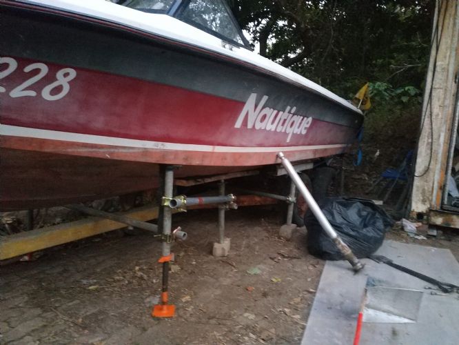 8 scaffold jacks and a bunk trailer on bricks , shape is good and not moving while i work 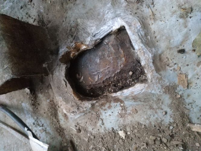 Pylon out easy with sawsall and datum still there to put it back  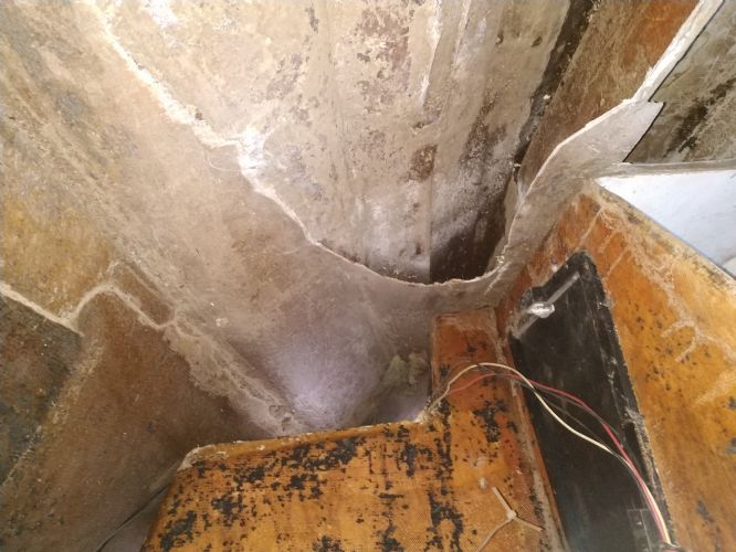 upside down ... floor in the driver side foam out 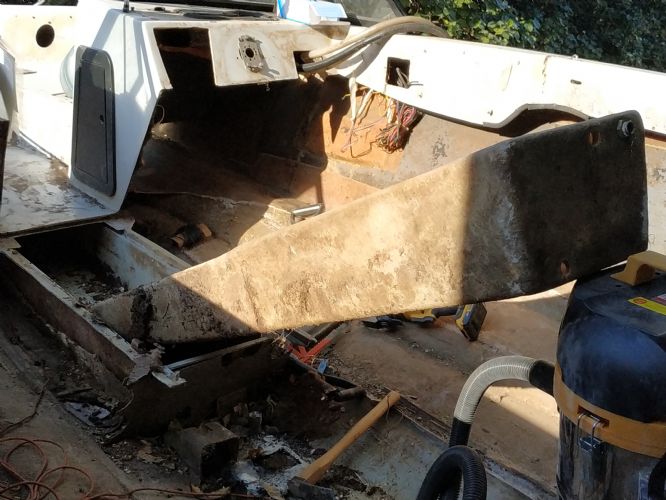 Tank build in the locker is finally out !!! 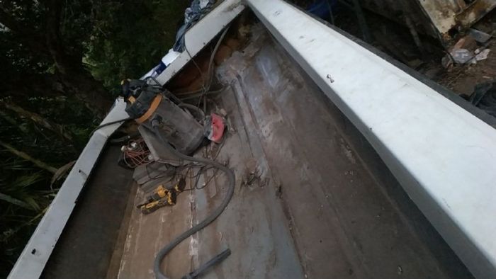 Big cleanup starting aft port |
Posted By: Ian H
Date Posted: January-02-2021 at 8:09am
|
Just as I was about to congratulate myself on finishing the surface prep for the floor and stringers in complete white out . I was hit with a curve ball.... the lifting points are mush. its a funny story I was really angry that when I acquired the boat it was lifted with strops without a spacer instead of the lifting points and the deck was damaged. If they has used the lifting points I think it would have been gave over. Sanding the last awkward corner I grabbed the lifting point to get to my feet and it came off in my hand! .... pulled completely out of the mounting. Port and starboard the same. Seems the lifting points were plywood and in my boat they were wet. Anyone know what the construction of the fore and aft lifting points are? I need a beer or two and a re-group.    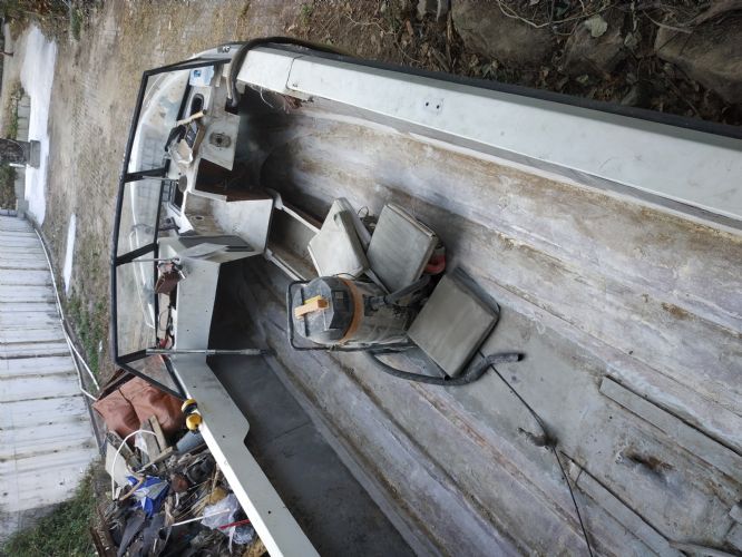  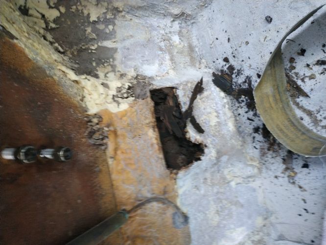 |
Posted By: MechGaT
Date Posted: January-02-2021 at 9:11am
|
I used the same mixture I used to bed the stringers to bed the plywood. I made the piece that goes under the seats out of one piece so it had to slide into place, making it a little tougher to bed down. The sections in the back were easy. As far as the method to trace the stringers, get a little trimmed off in the front and rear so there’s not a huge gap in the middle and use a compass to transfer the shape of the hull to it. Be sure to do both sides of the stringers. Others have replaced the lifting points in their rebuilding threads. Not sure if pictures are on the site still. If you are searching for things on here the best way is go to Google, type “site:correct craft fan.com topic” and replace “topic” with what you are looking for. On the lift points, I assume the main question is how to get the studs sticking out through the plywood. Countersink and washers is all I can remember from another thread. Also, think about how to apply pressure until the bond to the hull is dry. ------------- '92 Sport Nautique |
Posted By: Ian H
Date Posted: January-02-2021 at 5:49pm
|
Thanks For the floor I will try to make life a bit easier and an L shape a bit like the original I found in a factory tour video below. I still have to do my homework on peanut butter mix of chop cobosil etc (but need to stick to one step at a time or my head may explode. Engine and wiring also all moving along and parts piling up, but most important is to get the hull done while the weather is dry. and cool. I may put up another post to see if I can get some pics of the rear mounting I have not had any luck searching good advice on how to get the pressure on I had not thought about this but can rig something if I think in advance, My guess is that lifting points are just big pad of plywood stuck to the aft of hull and lots of g;ass over the top. I will cut them our today and see if i can piece it together. I really want o grind all the surfaces for new glass so i can properly clean up the itchy dust.! I am hoping the front lift point is not the same construction i hope it connects with the front bow u bolt. without any rotting wood. Thanks again Best pic i can find of the front mount i hope there is nothing woody holding it in |
Posted By: Ian H
Date Posted: January-03-2021 at 10:23am
looks lie the construction of the lifting point anchors is two sheets of ply with a bed of chop strand with a chamber on the sides and two or three layers of weave on top . all cut out and prepped for the replacements. some overkill wont go amiss here to be sure they are strong. Still not able to find ant post for this . Working in this tight corner is really unpleasant to far to do at arms length so end up close to the swirling dust cramped up in the corner. Nasty. after this i could pressure wash, one of the few beefits of working outside! now all clean and the inching powder is gone for now.  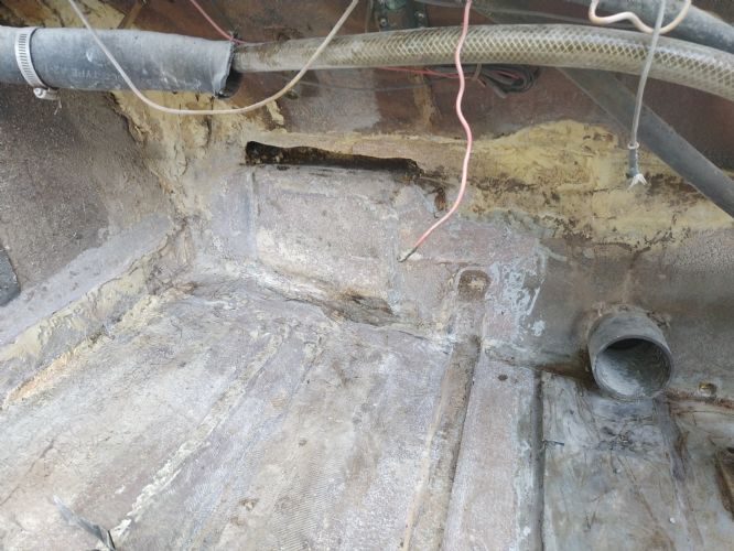 
|
Posted By: MechGaT
Date Posted: January-05-2021 at 12:19pm
|
On https://www.correctcraftfan.com/forum/forum_posts.asp?TID=16014&PN=3&title=another-bfn-rebuild" rel="nofollow - this thread there is a picture and sketch of the front lifting eye from a Barefoot Nautique. I have not seen the details on a Sport, but I imagine it to be similar, just tucked away behind the seats in the bow. I have seen another thread with details on how someone replaced the rear ones, but I can't seem to find it now. ------------- '92 Sport Nautique |
Posted By: MechGaT
Date Posted: January-05-2021 at 4:13pm
|
I found https://www.correctcraftfan.com/forum/forum_posts.asp?TID=12666&PN=12&title=my-new-2001-and-my-first" rel="nofollow - the thread I was looking for. In this one he rebuilt the rear lift points. ------------- '92 Sport Nautique |
Posted By: Ian H
Date Posted: January-06-2021 at 7:35am
|
Thanks, lucky you have a good memory that post is really useful i could not turn anything up just searching or googleing for the front mount i can see the bottom of the mount is really well glassed in and looks strong so I will just remove the u bolt ,and try to fill the void with epoxy re drill for the u bolt, ( cutting out and glassing in a small space is not my idea of fun!) This is what the fixing point looks like now.  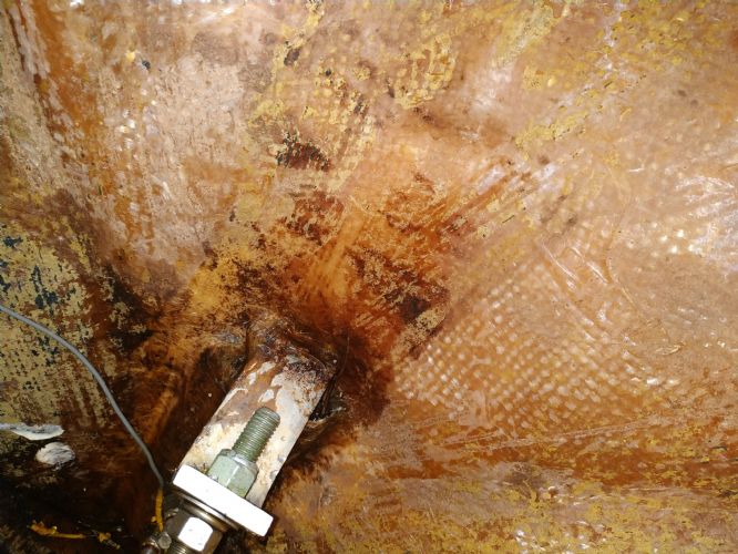 |
Posted By: Ian H
Date Posted: January-06-2021 at 8:54am
|
I have very little fiberglass experience. I have been trawling lots of posts and videos ... wow people can get really angry about the method and choice of materials!! and in the process get me very confused. I have decided that Epoxy is the way to go I plan to paint the wood until it wont absorb more or about 4 coats of Clear Penetrating Epoxy Sealer or acetone and epoxy I plan to bed the stringers in with a bed of peanut butter epoxy and Cabosil (fumed silica) ( not sure if adding chip would be good too) piped in from the corner of a plastic bag then drop in the stringer on top and hold it in place with a jig at the right height and position and smooth the peanut butter into a desert spoon sized fillet each side of the stringer. Plan to follow your plan for the layup "" as below but is there anything you would change with hind sight? Primary stringers: 2" 8.7oz E cloth, 4" 8.7oz E cloth, with each of these running the length with half on the hull and half on the stringer then 8" 8.7 oz E cloth overlapping 1" on the hull and up the stringer ~5". Over this lay 12" wide 1708 tape that starts at the top of the stringer and runs down onto the hull. That should make it overlap 1" past the 8" cloth. Same on both sides. Secondary stringers: same application of 2", 4", and 8" cloth and 12" biaxial. Then drape 7.5oz cloth over the top of the stringers to give them some protection. For the bulkhead behind the ski locker I plant to use plywood and use the 2", 4", and 8" on the seams to the stringers and hull then drape it in the 7.5oz cloth also. I am using plywood for the floor and plan to wrap it in 1.5oz mat. The fiberglass material I can measure and work out how much to buy but I am clueless on how much resin and CPES to buy I can see the CSM uses about 2.5 times the weight of resin for every 1 of fiberglass and for woven stuff about 1 to 1 so I can calculate ..... But in reality roughly how much resin , cabosil and chop did you buy ? also acetone CPES rollers brushes ? I need to ship in all my materials from China in a big lot and not easy to pop out for a bit more if I am short. an rough idea would be very useful. Did you buy tape in the right widths or cut them to the right widths? I have got 600ml mixing cups , i guess this is about as much as can be worked in the time before it goes off ,Dis you do the same? Sorry fro so may questions fiber glassing is not my superpower I need to get the stuff shipped in from China so getting
|
Posted By: Ian H
Date Posted: January-06-2021 at 9:01am

Now looking if I can rob a tower off an abandoned boat in front of my house. Not looking promising  Alibaba time... Alibaba time... |
Posted By: Timr71
Date Posted: January-06-2021 at 4:04pm
The key to this build is an Alabama trash can sporting a time period appropriate logo from the days when I was in school there. Just kidding. Good luck with your build. I like watching stringer jobs. You're doing a great job so far. Gonna be a great boat.
|
Posted By: MechGaT
Date Posted: January-06-2021 at 4:47pm
|
I am not an expert using fiberglass either. Including the work I did on my boat, I have done the fiberglass on one boat and nothing else. Epoxy made it easy. I bought the 1 gallon kit of CPES from Rot Doctor and I still have some left over after giving every piece of wood that went into it at least 2 good coats. For Epoxy I used US Composites and got about three orders. I think the first was like 5 gallons and then I had to get like 3 more gallons. It has been a few years since I made my first purchase so I don't remember exactly, but I would say 8 gallons would be the minimum you would need. I used the fiberglass tape that was already made to 2", 4", and 8" widths and the 12" biax. I would use the same layup schedule. It worked well and the cloth was fairly easy to handle. Like I said, my experience is limited so there may be someone else who chimes in, but my research prior to doing this showed this was a pretty common layup schedule for tabbing the stringers into the hull. Like I said, I used a lot of milled fiber in my peanut butter mix. I read in one of the posts that it would make a strong bond. It does, but I would also say it is harder to work with. If I had to do it again I would probably search for something better to use in the joints where the spoon rounds out the transition. I had trouble in this area with the surface being rough. I haven't done any research since then so I don't know what to tell you to use that would be formed more easily. You are making great progress. Keep up the good work. ------------- '92 Sport Nautique |
Posted By: 2001SAN
Date Posted: January-08-2021 at 2:23am
Pass on the tower. It is fugly as hell. Enjoying your progress though. These deep projects are always impressive! Good luck! D ------------- A little knowledge is a dangerous thing... 2001 Super Air Nautique 1989 Fairline Corniche 31 www.bannrivercruises.co.uk |
Posted By: Ian H
Date Posted: January-08-2021 at 8:45am
Tower was a long shot it's another problem to be solved, I am really looking for the biggest shade I can find to shade in the super hot Hong Kong sun. It would be good to find something that would fill up the holes where the tower was taken off. bigger issues to solve right now;
|
Posted By: Ian H
Date Posted: January-08-2021 at 9:19am
|
I noticed the pads the fuel tank sits on is plastic honeycomb I guess this has something to do with not soaking the deck with fuel? I have by change some aircraft floor a with aluminium honeycomb and a aluminium skin. I am planning to use this for those two pads. All my materials are listed out and I am now battling through Taobao to get the materials out of China. Looking at sourcing in the US tis is going to be a serious bill. I will post the cost direct from China when i get it all sorted. I have tied to source tapes as much as possible I expect i will need to substitute plan with whats available. One really useful tip is a cardboard copy of the floor shape, It made thinking trough sides and coverage much easier and should help me get the first approximation of the new plywood floor. Tomorrows job is mark and cut the stringers, really looking to adding rather than taking away  ???? still need a bit of help on floor glassing. I think I am clear on how to glass in the stringers but still a bit uncertain about plywood floor, I assume CEPS the plywood and then install on peanut butter and top with the 1.5oz woven fiberglass but should there be a drape down from the floor to the primary stringer / bilge and up to the hull around the sides? Or is the plywood wrapped like a parcel in the 1.5 oz? Cardboard memory jogger  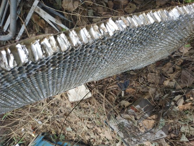 |
Posted By: 8122pbrainard
Date Posted: January-08-2021 at 12:51pm
|
Ian, Coating the ply with CPES will do the job of keeping the water out. Wrapping the ply like a package with glass is to add strength typically if you are going no foam. If the cavities are foamed, then it adds support to the ply. ------------- /diaries/details.asp?ID=1622" rel="nofollow - 54 Atom /diaries/details.asp?ID=2179" rel="nofollow - 77 Tique 64 X55 Dunphy Keep it original, Pete < |
Posted By: Ian H
Date Posted: January-10-2021 at 8:22am
|
I invested time in setting up for stringer and positioning, I glued in some braces tot eh hull and then added form to them so that the primary and secondary stringers have a positive position to but up against when I peanut butter them in. I can make sure the height is correct as J have marked the top stinger height on each of the braces. I was concerned that I will be scrabbling round trying to get stuff in the right place against the clock with sticky hands when I wan to be smoothing the fillets on the bottom corners of the stringers.. I think it will work out it should also help me with marking and fitting the stringers. I set the levels and positions of the primary stingers by putting the engine frame back in place to the datum's and dimensions i took before breakdown and then using this as the base, seems to match up ok with the old floor level which was a relief! This all took me two days of graft but I think it was a good investment. 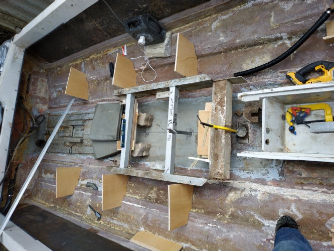 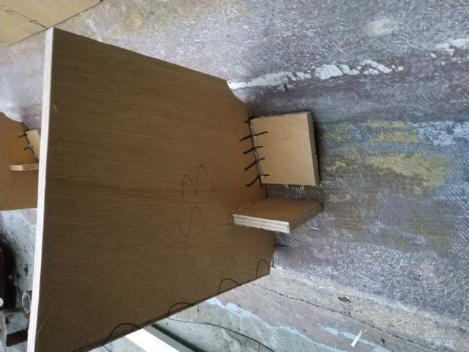  Marking out the hull shape on the stringers I guess I will just lift the stringer parallel to the level line on the guides and mark the the right offset to get the right depth? But its a big bit of wood so I think I will employ extra hands |
Posted By: MechGaT
Date Posted: January-10-2021 at 11:22am
|
That looks like a good plan to help you get the right spacing. I would recommend trying to get a basic shape on the bottom so that one of the bottom edges is close to the right line, I used a circular saw for this. Then lay it in next to the spacers you have made and use a compass to measure from the top of the stringer down to the line that is the level of the stringer (assuming you have already subtracted for the plywood that goes on top). Check this at each spacer. Now use the compass to scribe the cut line on in the inside and outside of the stringer. This will give you a line to follow the curvature of the hull. Don't forget that the fiberglass does have some thickness so that if the stringers are right up against the engine frame, it could be difficult to drop it in. It is not a lot of thickness, but I have seen other threads where this has been an issue. As far as your question about applying the fiberglass to the floor, yes, I draped the cloth down the sides of the stringers to the bilge and up the wall a little. I also put a layer of fiberglass on the plywood before installing, but that may not have been necessary, apparently. I looked at it as a layer of protection from moisture. ------------- '92 Sport Nautique |
Posted By: MourningWood
Date Posted: January-11-2021 at 2:24pm
|
Impressive work!!! I have to say, this may be the most ambitious project I've seen here. As a collection of the work required, the challenging working conditions (no offense meant at all), parts and supplies availability, etc. Great job!! ------------- 1964 Dunphy X-55 "One 'N Dun" 'I measured twice, cut three times, and it's still too short!" |
Posted By: Ian H
Date Posted: January-12-2021 at 6:49am
This project is really testing my ingenuity and tenacity. I dream of a garage with a bench and vice .  Main objective now is not to think myself into a standstill, and keep moving forward. Floor in with the engine frame in the right place will be a massive landmark. Wiring is coming along slowly. Engine is now waiting for the last parts to arrive hopefully just as the floor is finished. Thanks for the encouragement! Main objective now is not to think myself into a standstill, and keep moving forward. Floor in with the engine frame in the right place will be a massive landmark. Wiring is coming along slowly. Engine is now waiting for the last parts to arrive hopefully just as the floor is finished. Thanks for the encouragement!
|
Posted By: 8122pbrainard
Date Posted: January-12-2021 at 6:58am
|
Ian, I too am impressed especially with the progress you are making. Do you have any help or doing all this yourself? If yourself, are you getting any sleep?  ------------- /diaries/details.asp?ID=1622" rel="nofollow - 54 Atom /diaries/details.asp?ID=2179" rel="nofollow - 77 Tique 64 X55 Dunphy Keep it original, Pete < |
Posted By: Ian H
Date Posted: January-17-2021 at 10:22am
|
No helping hands so far I'm afraid but I am lining up some for the glassing part. The advice on how to mark the stringer shape was good and together with my fixture jigs it went OK for the two primary stringers, the fit with the hull is good gaps of no moper than about 4 mm credit card cut to the offset worked really well But I will need to sort out the height but can do this on the flat top with a circular saw. I intend to put some stainless round head screws on to fix the distance of the stringer to the hull when I squish down on the peanut butter. I guess about 2 or 3mm bed of 1/4 chop and Cabosil will be ok. I worry that I will lose all my levels when I come to assemble. I am not an experience glassing guy so I am trying to fix as much as possible rather than last minute adjustments. I used a laser level to check and correct before I set in the stringers etc. Cost about 40 USD worth every penny able to check lots of different points outside and inside the hull. great fro checking the floor is going to line up with the stringer and floor stack all around. 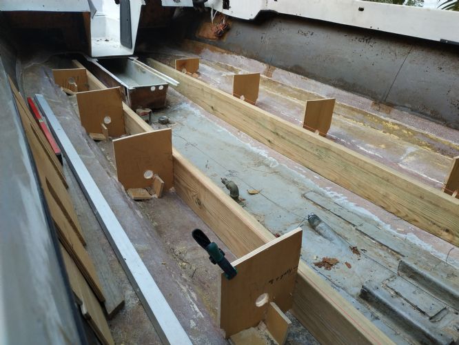  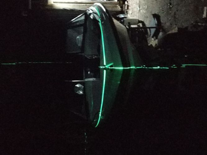 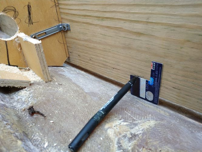 Things to fill the dashboard holes have now all arrived, lots of changes to wiring harness to get it to connect up. Struggling to find anywhere that will engrave the laminated plastic packs. 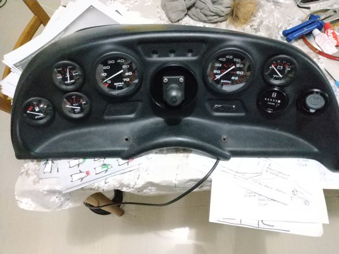 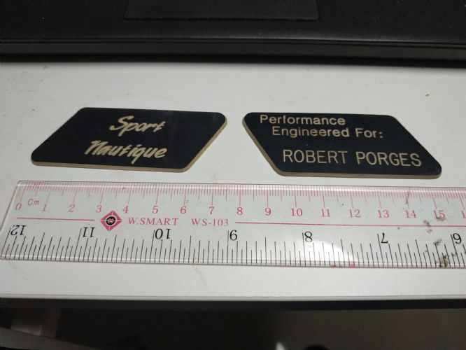 |
Posted By: jimsport93
Date Posted: January-17-2021 at 12:00pm
|
Marty Mabe, member of this site, may be able to hook you up with the engraved dash plaques. ------------- http://www.correctcraftfan.com/diaries/details.asp?ID=2798 - 93 Sport Nautique |
Posted By: ultrarunner
Date Posted: January-19-2021 at 11:49am
|
Yep, Marty will hook you right up. Now, I'm liking the gas tank in the locker. The Sports are always heavy in the back. Not as much on the slant-backs, but certainly on the round backs as so much 'stuff' gets put in the locker. And mine also had the ballast tanks and plumbing back there. I'd imagine a good change to the wake with no weight back there and fuel in the center of the boat....
|
Posted By: Ian H
Date Posted: January-20-2021 at 7:14am
|
Thanks for the feedback on the tank , I needed to decide now to put the tanks back in or not..... I plan to put it back in. I continued and finished off the secondary stringers much easier after the cycle of learning on the primary's and I am looking ok level after some super thin cuts off the flat top of the stringers I have all my round head SS screws setting the spacing for the peanut butter and the stringer holding jigs hold each stringer in place with just two screws so I am quite confident I can get the positions right when I glass them in. I will now start lifting points and locker bulkhead. All the glass, fillers and epoxy are sourced out of China using TaoBao but I have had a lot of help from a Hong Kong Chinese friend. I have more than enough to keep me busy till it arrives in about a week.  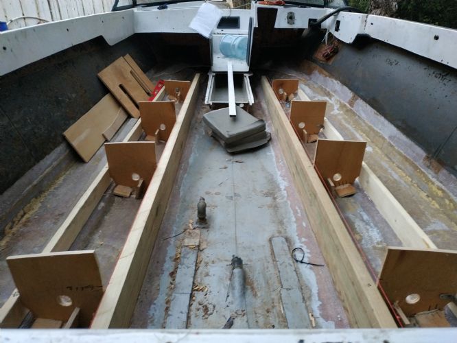 |
Posted By: MechGaT
Date Posted: January-23-2021 at 7:25am
|
Looking good.👍 ------------- '92 Sport Nautique |
Posted By: Ian H
Date Posted: January-26-2021 at 12:58am
|
Thanks, finally I am happy with the fit and the level of the stringers, I cannot really do anything on the floor fitting as my stringer positioning jigs are higher than floor level. I have finished the lifting mounts and rounded of the tops of the stringers to help with the glass. I have been working on finishing the wiring, basically all redone from scratch badly corroded and endlessly cut about with lots of twisted fixes  . So all new. . So all new. I have one simple question . Where should the battery be? there was a tractor battery under the passenger side and an isolator but no mount to fix it in place and all battery cable corroded solid. A photo of the fitted battery would be really helpful.
|
Posted By: ultrarunner
Date Posted: January-26-2021 at 8:04am
|
Hi Ian, you're making some great progress and your workmanship looks really good. Regarding the battery, on Sport's the BATT would be located under that forward most hatch in the center of the bow. If you look in there, you might find evidence of that by holes drilled into the glass where that BATT cables would have been run. This is the BATT location on slightly newer Sport's, and I'm guessing similar on yours. It's a good spot. Others have also added second batteries in the adjacent lockers, if you thought you would have a need. One of the folks on here will shoot you a picture of their setup on that generation of Sport. Keep the pics coming Ian. Mark This was a change from the typical Ski Nautique which has the BATT in the general location of the aft portion of where the ski locker is on the Sport.
|
Posted By: dockedwages1
Date Posted: January-26-2021 at 8:07pm
| I’m in the process of cleaning up my wiring harness. Can you tell me where to get appropriate wires and if you used heat shrink tubing to kind of keep everything together? |
Posted By: MechGaT
Date Posted: January-26-2021 at 9:42pm
|
On our generation of Sport, the battery is located in the rear, under the center of the rear seat. I am on my phone and can’t post pictures, but the two blocks of wood between the rudder and shaft penetration are the blocks that hold it up off the bottom of the bilge. I am not sure my arrangement is factory. When I get some time I will try to find a picture of my battery. ------------- '92 Sport Nautique |
Posted By: ultrarunner
Date Posted: January-26-2021 at 9:49pm
| Hmmmm, battery located in the area of the gas tank would not seem ideal, or factory. Things that would keep me up at night! |
Posted By: KENO
Date Posted: January-27-2021 at 8:17am
For those times when you want to stay up all night just print this picture out and keep it in a handy spot for quick reference.  I think this is a 94 Sport Nautique factory location like MechGaT mentioned for his 92 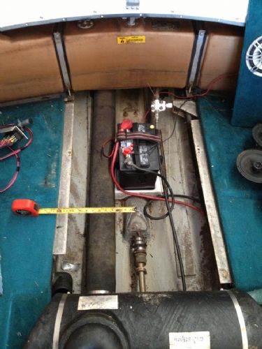 |
Posted By: ultrarunner
Date Posted: January-27-2021 at 8:42am
| Wow! Some engineer needs a spanking for that brain-child of an idea! I’ve see batts fail. It’s not pretty. Less pretty next to fuel would be my guess;-) I’m guessing the factory saved a few bucks on copper cable with that short run. |
Posted By: samudj01
Date Posted: January-27-2021 at 8:56am
|
Same location for the mid/late 80s Martiniques. ------------- 78 Ski Tique, 72 Skier w/302's, 93 SN w/351 & 17 GS22 w/zr409 Previous - 99 Sport Nautique w/GT40 and 87 Martinique w/351 |
Posted By: ultrarunner
Date Posted: January-27-2021 at 8:58am
| Learn something every day! |
Posted By: 8122pbrainard
Date Posted: January-27-2021 at 9:06am
Mark, What falure are you speaking of?
------------- /diaries/details.asp?ID=1622" rel="nofollow - 54 Atom /diaries/details.asp?ID=2179" rel="nofollow - 77 Tique 64 X55 Dunphy Keep it original, Pete < |
Posted By: ultrarunner
Date Posted: January-27-2021 at 9:35am
| I had a lead acid catch fire a bunch of years ago. Wasn't in a boat. Nicads can be nasty also. The AGM's might be a better option next to fuel. |
Posted By: 8122pbrainard
Date Posted: January-27-2021 at 10:05am
Mark, I've been around boats for around 60 years and have never seen nor heard of a battery problem causing a dangerous situation. I feel you concern is unfounded. ------------- /diaries/details.asp?ID=1622" rel="nofollow - 54 Atom /diaries/details.asp?ID=2179" rel="nofollow - 77 Tique 64 X55 Dunphy Keep it original, Pete < |
Posted By: ultrarunner
Date Posted: January-27-2021 at 10:10am
|
You could be right. I was just thinking 'big picture' of an electrical source and fuel source in such close proximity, in an area not well ventilated. Clearly, however, we're not seeing issues with all these older boats with batteries in the back. Mark
|
Posted By: MechGaT
Date Posted: January-27-2021 at 5:36pm
|
I always wondered if it was supposed to have a battery box. It is good to know that my boat is not the only one without one. ------------- '92 Sport Nautique |
Posted By: Ian H
Date Posted: January-31-2021 at 6:56pm
|
I have had to almost completely redo the wiring but I have managed to keep the original big connectors. I used the heat shrink crimp connectors in the photo below. You need a good heat gun to melt the glue and get them to seal. they are great as they are rock hard and impossible to pull the wires out of the crimp after they hare shrunk. It is much easier to get good joints with the think ring crimp like the RS pro ones in the photo the crimp is always good the think one are a bit variable so worth hunting these down. One other tip is that where you need to splice a wire to the old harness and there are oxidated black wires normal flux is not good enough to allow a solder or the crimp has a bad resistance. I was very successful in solving this by soaking the stripped ends in vinegar and salt solution for a few hours and then soaking in bicarbonate of soda to neutralize the effect. I was able to get perfect tinning for my soldered splices like this. Saved the day for me! 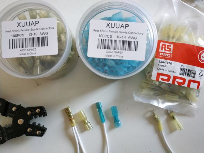 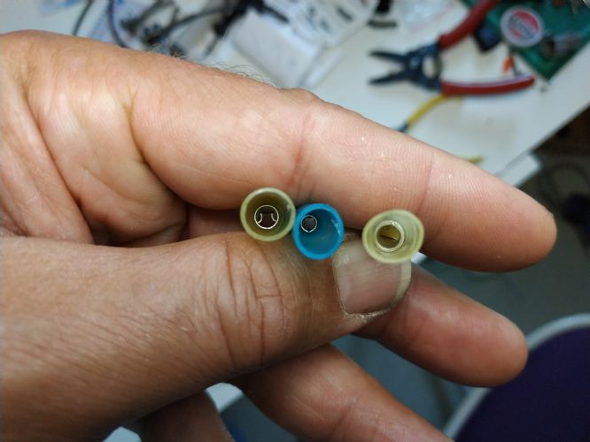 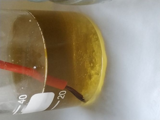  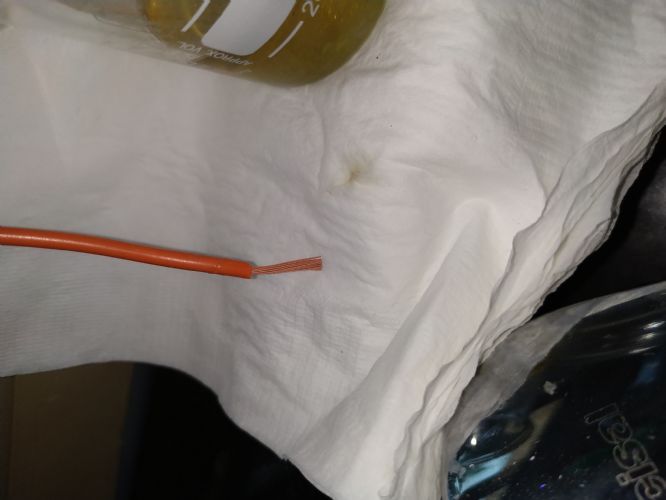 |
Posted By: Ian H
Date Posted: January-31-2021 at 7:05pm
|
Thanks for the picture I was wondering what those two blocks were in the bilge. I have now filled them with resin and chop to put them to use. going to be tight with the rudder cable clamp....  New lifting mounts are made ready to glass in and floor is cut to first rough fit. 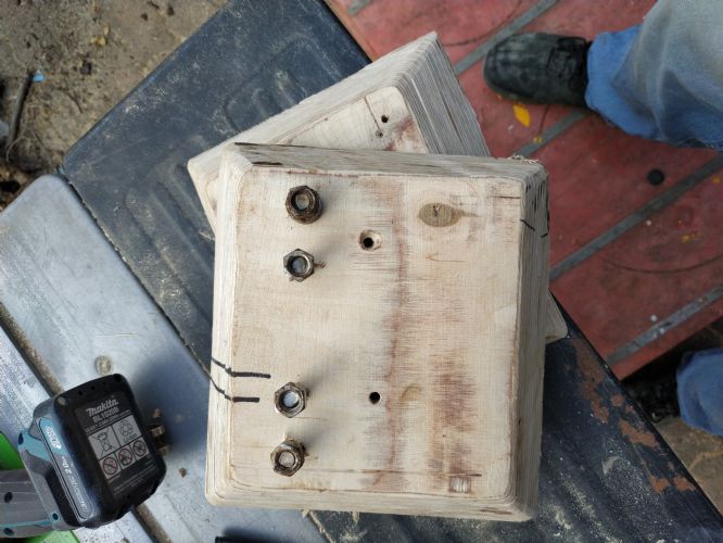 |
Posted By: 8122pbrainard
Date Posted: January-31-2021 at 7:19pm
|
Ian, Good work with the adhesive lined heat shrink crimp on connectors. It's an item I always recommend. Yes, the old wire can be a real PITA. Thanks for the tip. It's too bad there aren't many boat builders that go for the extra cost of using tinned marine grade wire.
------------- /diaries/details.asp?ID=1622" rel="nofollow - 54 Atom /diaries/details.asp?ID=2179" rel="nofollow - 77 Tique 64 X55 Dunphy Keep it original, Pete < |
Posted By: Ian H
Date Posted: February-06-2021 at 7:38am
|
Finally rebuild time. Peanut buttered the new lifting points into place ready for glassing in tomorrow. managed to squeeze them in good and tight and hold them with a cam effect lever pivoted far away on the stringer. the excess squeezing out of the sides gives me confidence there should be no voids. Floor is now dry fitted on top of the dry fitted stingers spaced with packing to allow for the Fiberglas layup thicknesses. levels came up pretty good so I could route out the thickness of the old floor to join the ski box to the new floor. Ugly now but should be strong I hope All my materials have just arrived from China just before the big slow down for Chinese new year. Epoxy is not the low viscosity I was looking for but is great for peanut butter. Lamination is not possible with this treacle so managed to find a source in Hong Kong for West System which works fine but not sure its going to be enough, ??? Is there a problem to use the thick epoxy for the peanut butter and put the low viscosity laminating epoxy on top?
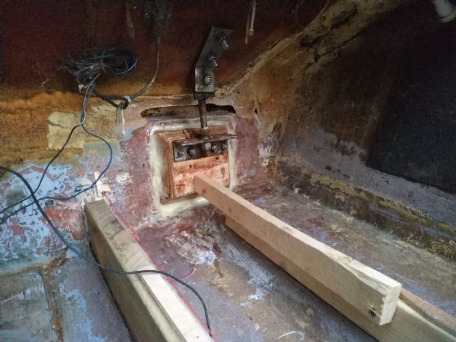 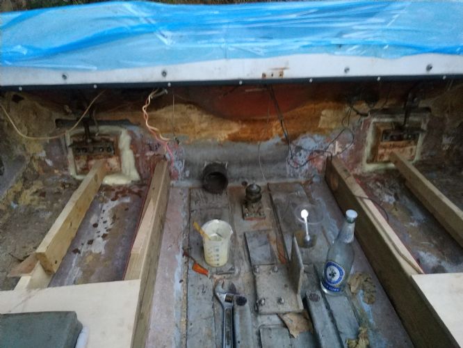  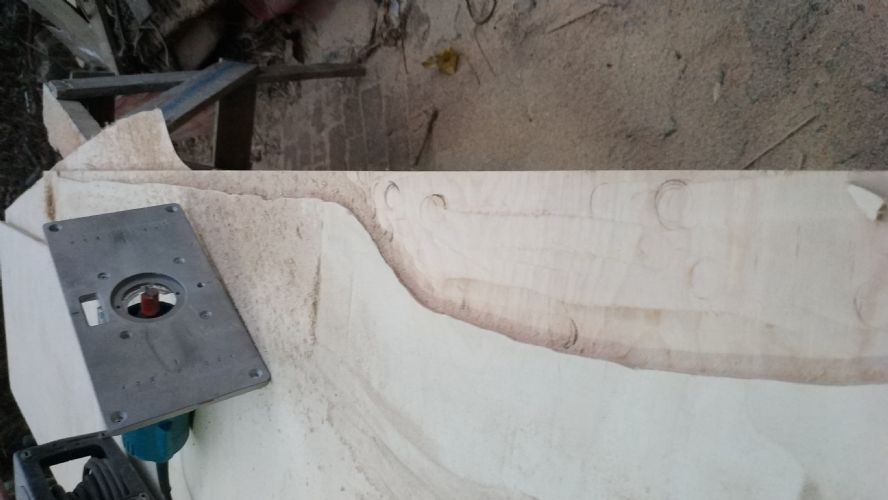 |
Posted By: C_Heath
Date Posted: February-09-2021 at 2:14pm
|
awesome thread IAN! keep it current and dont make us come to hong kong for updates! ------------- 1979 Calipso Runabout (the boat that got it all started) 1988 Mastercraft ProStar 190 (sold) 2000 Pro Air Nautique/GT40 |
Posted By: Ian H
Date Posted: March-02-2021 at 9:51am
|
I am still batting on, after convincing myself epoxy is the way to go, I ordered out of China it only to get the wrong thing with a consistency of very stiff treacle even when heated in a bath of boiling water. Penetrating epoxy also was not what I was looking for. The failed attempt took some weeks but i found a source for West system in China and a method of shipping it out but Chinese new year then fell and everything ground to a halt. My estimate is I need about 30ltrs all in all to the job done I now have the first 3.7 in hand (US Gal) I am crossing the rest will turn up this week. In the meantime I have had time to plan better. I decided the air vents are one of the best paths for water into the under floor space so I have used 3 1/4 drain pipe which should let me seal the water upstairs. I dont have a photo but the back two vents are the same plastic drain pipe and 90 degree bends.  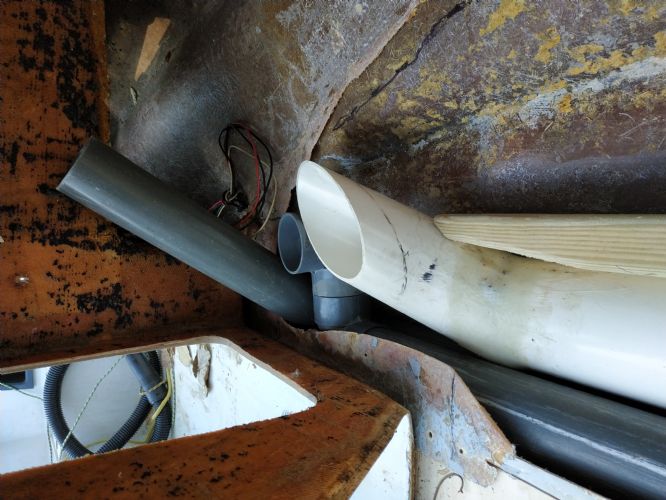 The pylon foot used the last epoxy I had. Then I had to start on other stuff. 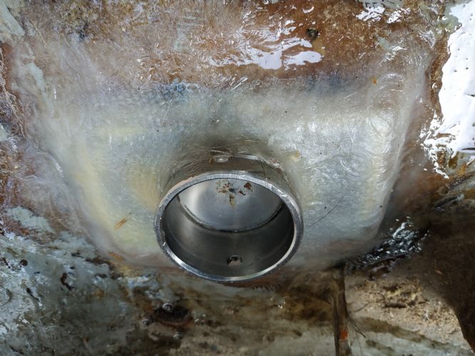 I managed to get the new cutlass bearing in with the technique recip saw and threaded bar learned on CCF   I could get 2 4 6 and 8 inch fiberglass tape to layup the stringers but bilabial came in a 1.5 m roll so I have cut the forms to drape over and get the constant overlap at the hull without too much excess at the top when the stringer high gets short. ( Three pallet table on top of a dead fridge works    Now just need resin... Then on to engine. not perfect engine building conditions outside under a tarpaulin but it rained to damp down all dust just at the right time. Big relief when I got it all closed up from the elements. Not pretty but I hope should be reliable. Sierra Distributor and coil, new alternator, starter oil pump, raw water impeller pulleys ...... valve covers are too tall and just hit the exhaust manifold but I have another set of Edelbrocks on the way that should fix this. The PCM alloy ones were corroded too badly to save. 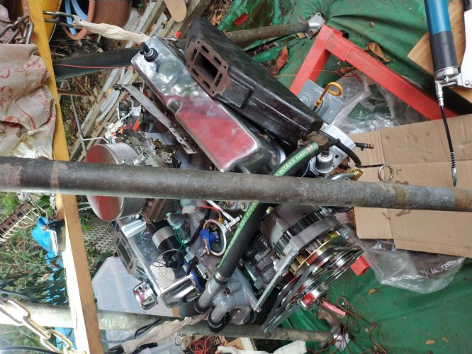 Bounce on the engine support started to freak me out so the tripod came out early as additional support . 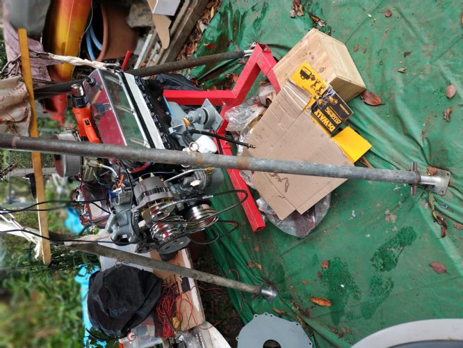 I had most of the cast iron parts sand blasted and I then repainted. Engine mounts with new rubber worked out well  Oh and in my spare time I completed the full electrical rebuild on a board ready to hook up with the engine for an out of boat start up. 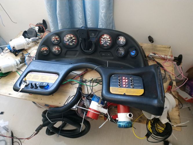 I hope my next news will be to show the stringers and floor going in..... I hope my layup thicknesses work out to the floor height comes good.
|
Posted By: Ian H
Date Posted: March-02-2021 at 10:01am
Dry floor fit up looks like this, not sure yet how to join the two butt ends of plywood floor together..Peanut butter on top of the foam?? 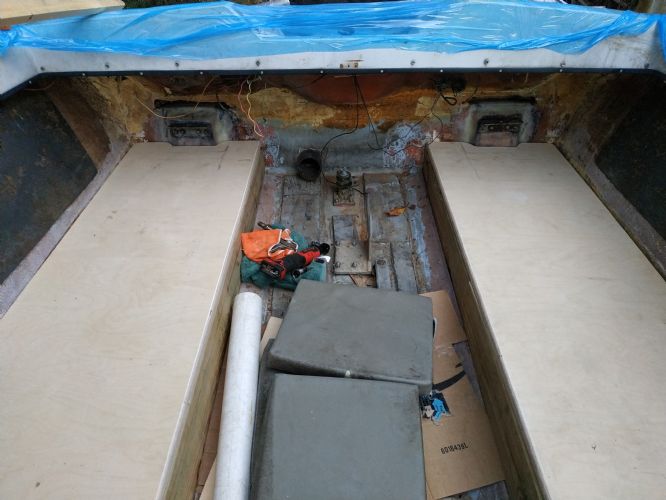 |
Posted By: MechGaT
Date Posted: March-02-2021 at 10:16am
|
Looking good on the progress! For the ends that butt up, once they are glued down with the epoxy peanut butter, take a little more and smooth out the transition. Then fiberglass over them and if still not as smooth as you want, use some fairing compound. If you are putting in carpet it doesn’t have to be perfect, just smooth enough it won’t be noticeable. ------------- '92 Sport Nautique |
Posted By: uk1979
Date Posted: March-02-2021 at 11:19am
|
Look at this thread it has Tim's link on home brew CPES, https://www.correctcraftfan.com/forum/forum_posts.asp?TID=20669&title=home-brew" rel="nofollow - https://www.correctcraftfan.com/forum/forum_posts.asp?TID=20669&title=home-brew You may be able to thin the treacle after you have added the hardener first... best run some tests, I found my Epoxy worked best as a CPES @ 80% Xylene to 20% Epoxy... Do all your mixing/working outside this is not good stuff to breath.. some use other types of thinners too. Good luck with it. ------------- Lets have a go 56 Starflite 77 SN 78 SN 80 BFN |
Posted By: Timr71
Date Posted: March-16-2021 at 9:49am
| Hi Ian - any updates. You seem to be making such good progress on this one. |
Posted By: Ian H
Date Posted: March-18-2021 at 10:35am
|
Yes I am still pushing on. The sticking it all together bit is quite stressful and after all the effort to get the bits to fit together I was a bit nervous on my limited glassing skills. Resin finally turned up I manged to gather together 32 liters of 105 West system Epoxy close to the 8 gallon estimate from MechGa T Lets see If it can do the job! Epoxy was a very good decision, working outside were ambient goes from 17 deC up to close to 28 in one day with direct sun I could tweek the mix enough to give enough time to work and go off in an hour. My prep on the position of the stringers worked perfectly and with the stainless screws adjusting the gap for the peanut butter I could get the stringers bedded in exactly on the planned position just screwing down on two screws in 30 seconds leaving enough time to smooth the fillet and get the first 2 inch tape on before the butter started stiffening and avoided any rework. 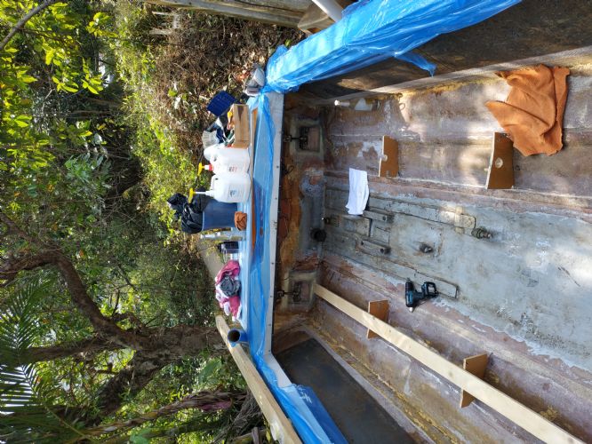 Everything ready on the start line mixing table on the stern of the boat to minimize time climbing in and out 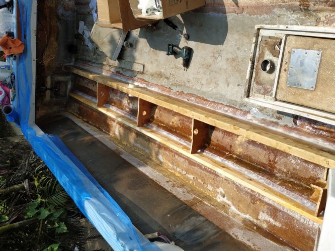 Peanut Butter and 2" tape in on secondary and primary cut outs on the holding jigs allow the 2" tape to be threaded in to give a good robust bond before knocking out the position jigs. Then marathon of laminating I followed the plan courtesy of MechGa T + as I could not source 1708 an additional layer of bi axial. Pre cutting the shapes to fit the stringers with tabs was a good prep as no time to um and urr or think about cutting shapes.  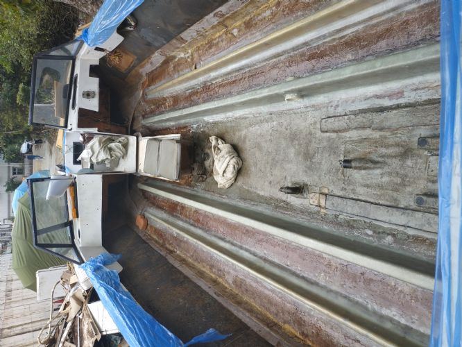 Here is the result  My stack calculation worked out good I was aiming to have the same 6mm wall thickness on the top of the stringers as the originals and I was pretty dead on so the floor still fitted and the engine frame mounting points look good and space between the stringers is dead on. I made a jig to calm my nerves so i could check as i went along .  I used hard drainage pipe for the ventilation which I then glued up ready for the floor to go in I used hard drainage pipe for the ventilation which I then glued up ready for the floor to go in 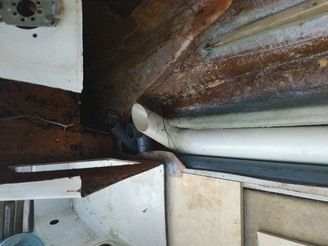 I bought enough polyurethane expanding foam to fill the voids but High ambient caused overheating and my tests expanded ridiculously quickly which could deal with but the foam over expanded not leaving closed cells so the foam deflated a short while after. I managed to do the essential bow end filling around the vent pipes in the bow. the other areas i fitted pre expanded foal board into the voids before putting the floor on top. I do not need the structure as I have 15mm birch board with a layer of glass on the underside too so I only need the emergency flotation properties of the foam. This allowed me to keep moving and get both sides of front floor down on peanut butter held down with cast iron drain grates  dark air full of mosquitos I will get a better photo later. I am so happy the levels look good and boat feels very rigid. Just got to find the energy to finish in the next window of dry weather. BTW my stingers were 8% moisture level after living in our bedroom with a dehumidifier so I think the bond will be good with the wood. dark air full of mosquitos I will get a better photo later. I am so happy the levels look good and boat feels very rigid. Just got to find the energy to finish in the next window of dry weather. BTW my stingers were 8% moisture level after living in our bedroom with a dehumidifier so I think the bond will be good with the wood.  On the engine front the gearbox is now on the engine and off the stand. Compression Wow Yes Fuel yes but no spark.... Can you believe the cruel trick that those nice guys at Sierra distributor paid on me... Yes the connector is correctly inserted But it took a bit of finding to see that green and red wires are swapped on the connector. 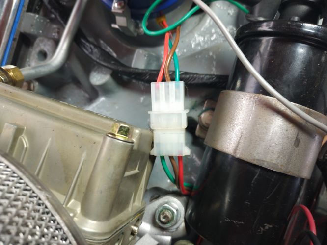 Electrical system on a board let me check that I had oil pressure and all the sensors on the engine work while manually priming the oil pump and cranking to try and start. . Good weather then switched all effort to hull I will start the engine on the next wet day. I hope.... I am now thinking of the next challenges..... How to get the engine into the boat and how to align the prop shaft with the engine. 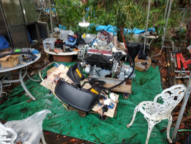 I dream of doing this in a garage with a bench a vice .... Many thanks for the encouragement and in particular for the layup plan from MechGa T it worked a treat even if i did laminate a lot of it with my bare hands (glove-less) to squish out the bubbles  Desperate laminating techniques! Desperate laminating techniques!Its warming up here so I need to finish the big stuff soon!
|
Posted By: samudj01
Date Posted: March-18-2021 at 7:54pm
|
Great progress. Enjoy following this. Keep up the good work! ------------- 78 Ski Tique, 72 Skier w/302's, 93 SN w/351 & 17 GS22 w/zr409 Previous - 99 Sport Nautique w/GT40 and 87 Martinique w/351 |
Posted By: NCH20SKIER
Date Posted: March-19-2021 at 5:59am
|
moving forward. keep pushing or pulling whatever the case may be ------------- '05 206 Limited '88 BFN |
Posted By: MechGaT
Date Posted: March-19-2021 at 7:09am
|
Looks like great progress. I noticed you are missing a strip of wood behind the ski locker. Do you have a plan to install some there? It gives the back of the locker support, and I think you will probably step in that area more than you think you would. Edit: I see now in an earlier post that you do have something to go in that area and have a plan, just haven’t installed it. ------------- '92 Sport Nautique |
Posted By: Ian H
Date Posted: March-19-2021 at 12:00pm
|
Well spotted , the top of the ski locker was originally plywood with fiberglass on top to make the bow floor. The wood was rotten , so I extracted it all and cut out a part of the floor over the locker by mistake when I took out the ballast tank. I cut a piece of ply to slot in about 90% in I put it in temporarily to get the space right when I reconnected the ski locker to the floor and fitted the front floor panelp ,but you have reminded me I still need to remove it and saturate it with epoxy. I plan to rebuild the step floor bit when I do the top fiberglass floor layer . I stood on the floor with just the hardened peanut butter today and it feels good . should be even better after the top cover of fiberglass goes in. |
Posted By: Ian H
Date Posted: March-20-2021 at 1:23pm
Floor is in, buoyancy using foam board cut with a sawsall and fixed with aerosol expanding foam where needed was quick and accurate and got over the variability problem using polyurethane in high temperatures. it was 28 in the shade today. 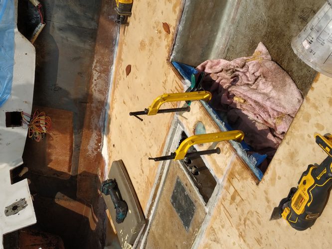 bridge with pylon hole is successful with three layers of bi axial layed up on cling film on a board and squeezed in with clamps from below. very stiff and thin enough to fit over the engine frame . |
Posted By: Ian H
Date Posted: March-20-2021 at 1:50pm
The back floor sections also with layer of fiberglass tissue pre applied to the underside then peanut buttered in, all vent [i[es are now in under the floor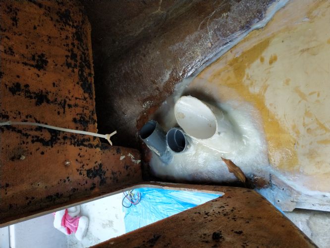 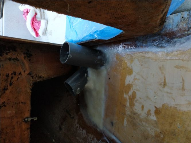   I hope to get the cloth on the top tomorrow. I would like the time to be a bit more pretty but Engine lift in opportunity with a Hiab is next week so I need to keep moving. I am now optimistic enough to think of propellers. This in the one I have, two blades were bent and I beat them back into shape forged in fire style. looks like a prop but i guess i had better change it. I want to do wake surfing with this boat, I have zero experience, Which prop should i get? I have no idea of the history of this one so no idea if it is good or bad selection. 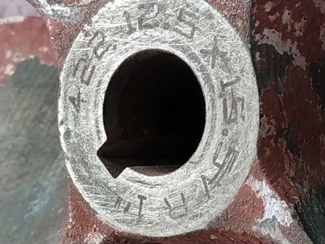 |
Posted By: MechGaT
Date Posted: March-20-2021 at 6:27pm
|
You are making a lot of progress. Like you said, hopefully you never need the flotation foam. That is an interesting idea for installation. I don’t know much about prop selection, especially for wake surfing. I do know that you don’t want to run one you have hammered out. The balance required to prevent vibration is very precise. The one you have is the same one I have and it works. That’s all I could say on selection. ------------- '92 Sport Nautique |
Posted By: Ian H
Date Posted: March-24-2021 at 8:56pm
As I am a novice I think I will start with the same prop thanks for letting me know you have the same I I got my top layer of glass on the floor. I ended up with a 100m roll of biaxial so I used it for my final layer. I was very close to running our of resin so it seems the 8 gallon total estimate was pretty good. Two coats of bilge coat have gone on after a small amount of faring as I am under time pressure. I am stunned that the engine frame went in as a slightly squeeky fit and when i put my gauges in and measured I am within a millimetre off the position of the frame original position compared to the prop exit and the floor. I put the screws in with lashings of silicone in the holes and between the frame and stringer. How to get the engine in. Hiab crane on the back of a truck is possible but scary as someone else will be on the controls..... and translation problems..... getting a a frame etc to hoist would be under my control but difficult to get together. I still have serious amount of stuff to do before I must do the engine so I have some time to consider. What I must study is how to do the alignment of the engine to the prop shaft. all my mountings are new so I guess i need to start from scratch. Is there a procedure to do it ? the old set up had two 10mm thick spacer plates on the engine side mounts only and the gearbox had none. Should I put the same spacer set up back in or start from scratch? You can see them in the pic below but nothing on the gearbox mounts 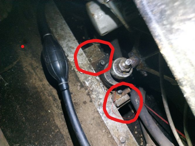 progress  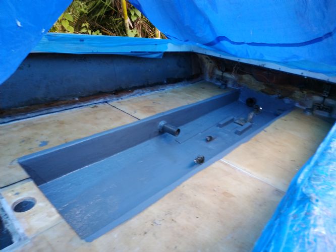 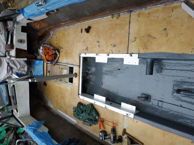 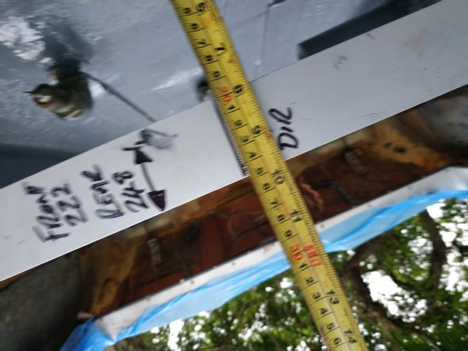 If anyone sees something i have missed or something i have done thats stupid please let me know!! |
Posted By: Ian H
Date Posted: March-25-2021 at 7:10am
|
Opportunistic lunch break engine lift with the grab garbage guy. Hong Kong Style !! Terrifying
Bolt holes not limed up yet but its in!!!!!! 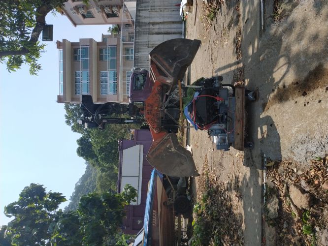  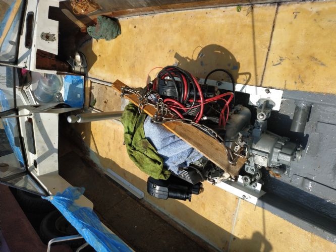 |
Posted By: ultrarunner
Date Posted: March-25-2021 at 8:13am
| WOW!! Quite the resourcefulness! |
Posted By: MechGaT
Date Posted: March-25-2021 at 1:11pm
|
I would start with the same spacers. There is a good bit of adjustment in the mounts. You might have a hard time moving them. Should have told you to give them a shot of penetrating oil and exercise them before dropping the engine in. Might have to work up a temporary support if they don’t move so you can take them out and get them free. ------------- '92 Sport Nautique |
Posted By: Ian H
Date Posted: March-29-2021 at 9:56am
|
Rear vent system in and tank and pipework went in OK shortly after. mow I am just working through assembly of all the bits. I am pleased with the sealed drainage pipes under the floor it worked out well and the floppy air duct was quick held in with cable ties and fixed in the corners with spray expanding foam.  Now I need to ask for some help. I have the remnants of the interior for the rear bench seat the and the bow but the diver seat observers bench and the dash for the observer side and side panels along the inside of the boat are a mystery as they we missing already. I cannot find good pictures or don not know quite what to do on the following Drivers seat looks like the seat is pretty much on the floor on a kind of wedge platform ? I can get a stainless plate mount folded up but a picture of what is there already would be very useful, also what kind of aftermarket seat would be a typical replacement? I found these bits (see below) of wood which I guess were the bench observers seat ? a picture would be much appreciated and I can try to recreate a new one. The observers dash panel I guess impossible to find a replacement I have nothing but a good photo might help me get creative the same for the kind of glove box thing. Side panels I guess were covered ply ? a picture of the back side of the engine cover would also be helpful I have the hinges and aluminium mounts but not sure how to mount them I also need to know how to build the bilge cover with access panel as mine was just a soggy carpet around an access hatch so I am not sure if this panel should go under the bench seat at the back and if the engine cover is screwed to it. If you could snap these for me I would be very grateful. ;  YES THAT IS A DOUBLE LAZYBOY ON MY BEACH FORGET THE PLASTIC BOTTLE PROBLEM IN ASIA FIRST WE NEED TO SOLVE THE LOUNGE FURNITURE ISSUE. New prop  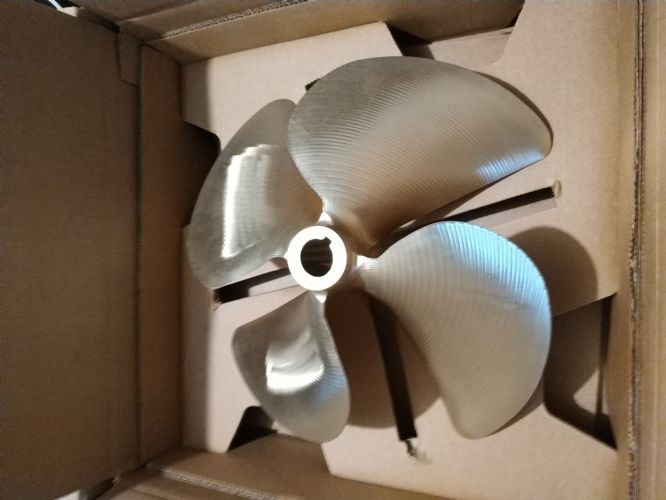 |
Posted By: 8122pbrainard
Date Posted: March-29-2021 at 4:35pm
|
Ian, I admire the progress you are making plus the resourcefulness you have shown in getting the materials for the project. Again, it's looking great. Be patient as I know someone will come through with some pictures to help you with the interior. ------------- /diaries/details.asp?ID=1622" rel="nofollow - 54 Atom /diaries/details.asp?ID=2179" rel="nofollow - 77 Tique 64 X55 Dunphy Keep it original, Pete < |
Posted By: ultrarunner
Date Posted: March-29-2021 at 5:39pm
|
Great work so far Ian.... So, you're correct. The drivers seat is mounted on a plastic wedge which is lagged into the floor. On top of that mounting "wedge" contains the rails that the seat slides onto, and can subsequently adjust with the side lever, fore and aft, along those rails. See attached picture. And yes, you could also have angles fabricated to accomplish the same. Here is also a pic of a 91 Sport with the single observer seat. I can't remember if the observer bench was offered that year. Someone will chime in with more info. Keep us posted, Mark Drivers seat mount. 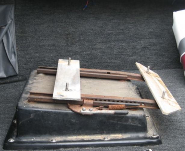 Front Dash Area.  |
Posted By: MechGaT
Date Posted: March-29-2021 at 10:10pm
|
I have been in a 1990 Sport and my ‘92 has the passenger seat that can face forward or backwards. As far as I know a bench was not offered, but I think it would be an upgrade if you could work one out. The storage behind it would be better, especially if it swung up like later models. I am on my phone so I can’t post pictures, but I will try to get on the computer tomorrow evening and post a few of the interior. ------------- '92 Sport Nautique |
Posted By: ultrarunner
Date Posted: March-29-2021 at 10:30pm
| A quick look in the ref section shows the flip-up bench in '94. Interestingly, in earlier years of other OB models...Excel, SNOB, there was a bench, but not on walk-thru's. |
Posted By: MechGaT
Date Posted: March-31-2021 at 8:42pm
|
Here are some pictures of the interior of my boat. The font: 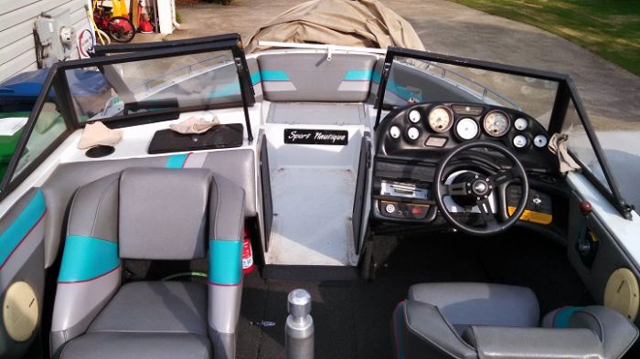 Looking back:  Seat base and seat, pay no attention to the messy room: 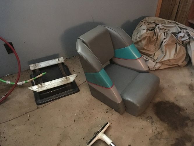 The rear area before the interior was put in. You can see the board that goes over the rudder on the left before I put carpet on it. On the right is the board that has the pins to hold the engine cover. This board goes just under the rear seat. 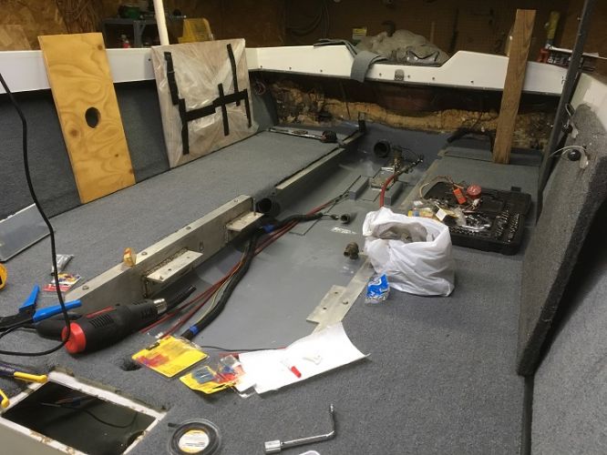 The rear seat is a plastic molded base. I don't have any pictures showing how it is made, but if you don't have one, that could be tough to recreate. ------------- '92 Sport Nautique |
Posted By: Ian H
Date Posted: April-01-2021 at 5:12am
Thanks very much, that is really helpful.  |
Posted By: Ian H
Date Posted: April-19-2021 at 10:32am
|
Easter I had 5 days of dinghy instructor training and exams I passed! I had to move my boat on its Ferrous Oxide trainer front wheel axles disintegrated and I had to haul it sideways with a chain hoist sideways to its new home in the corner. Two new axles from Taubau and I pray the trailer can make its last 30M trip into the drink  As all the engine mounts were completely refurbished and greased adjusting the engine to align the shaft went smoothly I think with the coupling collar just partially engaged in the transmission output flange the gap measured with feelers was a consistent fit all the way round and the shaft was centered in the stuff box tube and felt in a happy rotation position. Getting the drive coupling on the shaft was touch and go. first time i dis not use enough heat on the coupling and it jammed 50% on not going on and not coming off and getting cooler... but hot enough to burn  big plastic mallet and wild beating got it off ...... next time much hotter it just fell on big plastic mallet and wild beating got it off ...... next time much hotter it just fell on Exhaust is now on but adjustment was too low so gearbox direction lever fouled sorted with a lot of restricted spanner movement . Fuel lines and filter with water separator in 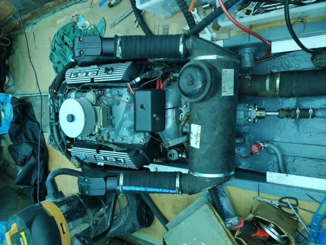 Green tinge is because I am working under a Tarp in the rain or trying to avoid the killer sun. All electrical is now in and working and the engine turns over and starts for just a second. I should finish the water inlet pipes including the filter and fresh water salt water divert valve. Then I can run the engine on the hose and I can tune the timing. Amazingly the original tower turned up in the back of a car, I think it was a greenhouse frame for the last few years and when the guy saw me working on the boat he kindly brought it back for me  unbelievable! This is double good news as my Chinese source had just broken the news that they could not supply me until July... unbelievable! This is double good news as my Chinese source had just broken the news that they could not supply me until July...   the foot spacing is perfect match with the holes already in the boat so I am sure it is the right one . My only problem is I have no deck mounting brackets I cannot see a brand on the frame ... is it a US frame anyone knows I am trying to get and idea of what brackets to make. Anyone have an idea? 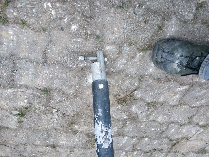 I am now hunting down a powder coat company to make a happy tower I had time for a quick buff looks like oxidation is going to come off ok with a good cutting compound 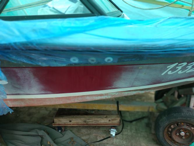 Driver seat spacing off the floor and angle I have worked out but the base is going to be a real workup The standard Nautique one will not work with the seats I could get my hands on and price with shipping is out of the question..... So I will spend the time to make some bases with ply and a thick layer of glass. 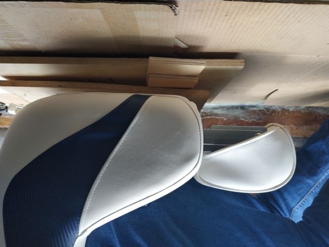 |
Posted By: Ian H
Date Posted: April-19-2021 at 10:38am
| Oh and carpet is ordered......... finishing line is still always just over the horizon. |
Posted By: 8122pbrainard
Date Posted: April-19-2021 at 11:01am
Ian, It looks like it's getting very close to seeing some water. Considering the fantastic job you are doing, I don'tfeel you will have any problems. It looks like it's getting very close to seeing some water. Considering the fantastic job you are doing, I don'tfeel you will have any problems. BTW, I'm curiouse as to what you are doing and do in Hong Kong?
------------- /diaries/details.asp?ID=1622" rel="nofollow - 54 Atom /diaries/details.asp?ID=2179" rel="nofollow - 77 Tique 64 X55 Dunphy Keep it original, Pete < |
Posted By: Gary S
Date Posted: April-19-2021 at 6:29pm
|
Chief translator/proof reader for Ding Bang Ow fortune cookie company ------------- http://www.correctcraftfan.com/diaries/details.asp?ID=1711&sort=&pagenum=1&yrstart=1966&yrend=1970" rel="nofollow - 69 Mustang HM SS 95 Nautique Super Sport |
Posted By: Jonny Quest
Date Posted: April-19-2021 at 8:49pm
https://www.youtube.com/watch?v=CaOkTKfxu44" rel="nofollow - https://www.youtube.com/watch?v=CaOkTKfxu44 ------------- Current 2003 Ski Nautique 206 Limited Previous 2001 Ski Nautique Open Bow 1994 Ski Nautique Open Bow Aqua skiing, ergo sum |
Posted By: Ian H
Date Posted: April-20-2021 at 5:28am
|
I'm British but work for a Chinese company making electric motors, our factory of around 26,000 people is just over the boarder from HK. I would normally commute into China a few times a week but not for the last 16 months! I am Head of Business Development, I have been here for about 8 years, I spent most of my career working for Honda Power Equipment and Engine division in Europe and Japan. Now I am busy replacing all those engines with motors and batteries! Thanks for the encouragement I beginning to believe I can finish. It wont be the best looking but I hope it will be tough and reliable. It has kept me sane though over a year of lock down...... next time I find a way to work inside with floor and a bench with a vice !
|
Posted By: Ian H
Date Posted: June-01-2021 at 8:01pm
I hav I have an overheating problem looks like the pump cannot prime from the water inlet in the hull. works fine on a hose , and sits at 160 degrees just like the rating of the thermostat but I made the mistake of not doing the bucket test and in the blur of pushing to get finished I did not look at the water inlet in the hull before i got it on the water. I am kicking myself as the trialer i used died at launch so no easy way to get it out, everything needs to be on the water for a few weeks at least. I have a new pump complete G21 on its way from SkiDim will arrive in a week or so. I will do the bucket test with a clear hose connected direct to the current pump and see if the problem is on the hull to pump side or confirm the pump is sick, But I need to check the inlet is clear. I have been down with a mask to have a feel around with a thin screwdriver but i really need to know what I am pocking to be sure what I am doing. Does anyone have a picture of the hull water inlet to guide me in my clean out dive. Its the one photo I do not have  I can blow bubbles from the raw water pump inlet pipe to the hull inlet and suck water the other way (yes i did put my mouth round the pipe) so it is not completely blocked but i want to be sure there is no obstruction. Gutted sea trial lasted 3 mins before i saw the temp rise to 200 . It was a fantastic 3 mins before the slap round the face  I hope it will just be the pump and inlet side as the hose cooling worked, I am trying to bock more complicated problems.
|
Posted By: Gary S
Date Posted: June-01-2021 at 8:55pm
|
Fantastic job Ian ! Don't go diving just yet. You might simply just have an air leak in an intake hose connection or the old pump it self. Much like trying to drink your favorite beverage through a straw with a pin hole in the side of it. Running on a hose masks that since it's under pressure rather than relying on the vacuum the pump creates. Is the pump mounted right? If it's a normal left hand rotation the pump will be mounted to it's bracket with the screw that holds it's internal cam in place toward the block. Did you replace any of those intake hoses? Do you have a strainer plumed in- is it sealed and not sucking air? Did you use a nut driver or socket to tighten all those clamps rather than a screwdriver? Check those easy things first and get the new pump on and see how it goes. This screw facing block - 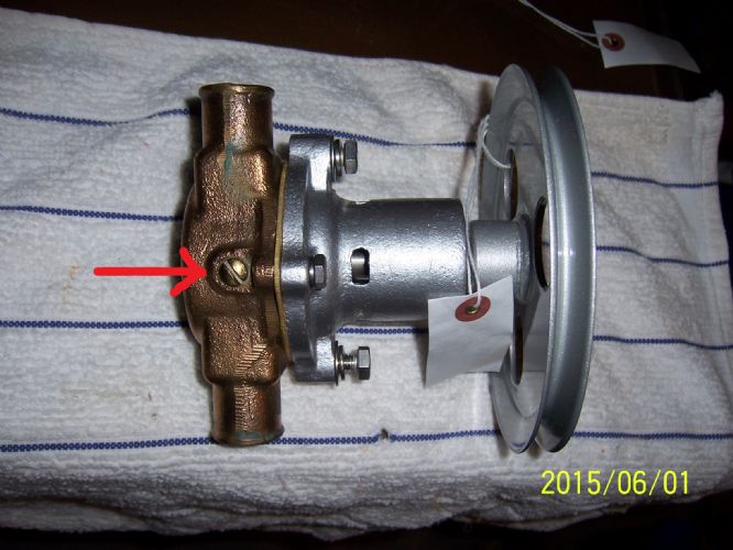 ------------- http://www.correctcraftfan.com/diaries/details.asp?ID=1711&sort=&pagenum=1&yrstart=1966&yrend=1970" rel="nofollow - 69 Mustang HM SS 95 Nautique Super Sport |
Posted By: Ian H
Date Posted: June-18-2021 at 10:44am
Thanks for the help Gary went through systematically and found that I had a air leak on an elbow going into the water strainer, This fixed it and for good measure the pump arrived from SKIDIM in an incredible three days so i fitted this too and the temperature is a solid 160 degrees and my blood pressure reduced  Thanks again for spending the time to help me out after complete rebuild my mid was racing about all the possibilities I now have my first 5 hours on the engine. Last snag is burning hot alternator. The new alternator I fitted on rebuild needs a 5 mm spacer to align the belt which I had missed , I hope this will solve this. If not I will be back.  So final result looks like this, many thanks to all who posted info help and encouragement to keep going and finish turned out to be a 5 month job the last month outside in 32 degrees C 90% humidity was very very tough. Its not the prettiest but it turned out the way I was hoping, where I have confidence that everything is fixed properly and reliable. Here is how it finally turned out. Cannot imagine how many times I climbed that shaky ladder  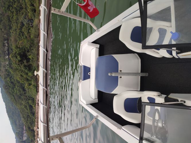 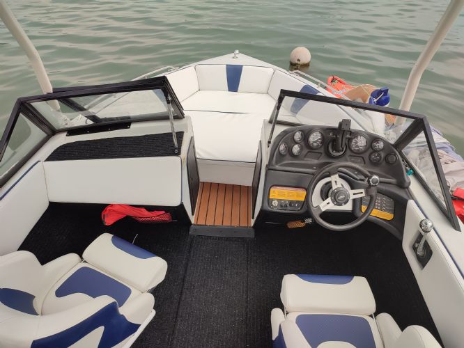 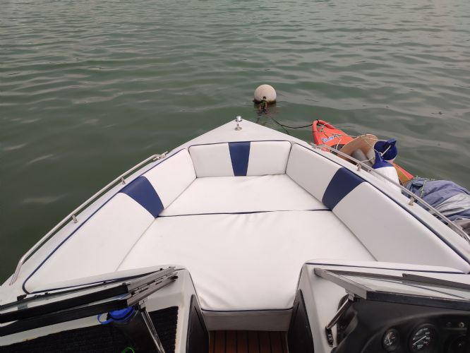    |
Posted By: ultrarunner
Date Posted: June-18-2021 at 12:00pm
|
Wow! Ian wins the prize for the best recovery and restoration, done under the most difficult conditions most of us can only imagine. Way to go. |
Posted By: Gary S
Date Posted: June-18-2021 at 1:43pm
|
Agreed, and it seems like in a relatively short time as well. Great Job Ian! ------------- http://www.correctcraftfan.com/diaries/details.asp?ID=1711&sort=&pagenum=1&yrstart=1966&yrend=1970" rel="nofollow - 69 Mustang HM SS 95 Nautique Super Sport |
Posted By: fanofccfan
Date Posted: June-18-2021 at 4:48pm
|
Bravo! it looks awesome! ------------- 2004 196 LE Ski 1969 Marauder 19 1978 Ski |
 MechGaT wrote: