96 SN ECU no power to FP relay
Printed From: CorrectCraftFan.com
Category: General Correct Craft Discussion
Forum Name: General Discussion
Forum Discription: Anything Correct Craft
URL: http://www.CorrectCraftFan.com/forum/forum_posts.asp?TID=51726
Printed Date: November-30-2024 at 5:41am
Topic: 96 SN ECU no power to FP relay
Posted By: Grover
Subject: 96 SN ECU no power to FP relay
Date Posted: August-13-2024 at 5:44pm
|
New member here. For the past few years my 96 SN would not run intermittently. I changed both the FP & Ignition relays several times. Sometimes that would work and other times it wouldn't start for a couple hours or days. There's no power to pin 85 or 86 on the fuel pump relay with key on. When I jumper the FP relay it turns on the pumps for 1-2 sec then shuts off, but I can still start the boat, I just have to pull the jumper to shut off the boat. Does that means the ECM is bad, and not activating the relay for some reason? Can I run the boat indefinitely with the FP jumpered? Any help is appreciated... |
Replies:
Posted By: KENO
Date Posted: August-13-2024 at 8:09pm
|
Power to pin 85 comes from the ECM relay output (pin 87)so if you don't have power at pin 85 and you're jumpering power to the fuel pump that would be telling me that it's not an ECM issue, but an issue with the wiring from the ECM relay to pin 85 or that the female socket that the fuel pump relay plugs into is bad (broken wire, dirty corroded female receptacles) The ECM relay is powering the ECM since your engine will run so like mentioned above check the wiring between the ECM relay pin 87 and the fuel pump relay pin 85. Is it safe to assume that you have the 310 page gt40 manual? How are you getting power to the fuel pump with your jumper setup? What you're doing obviously works for you and you could keep doing it but it's not the safest thing to do. If you have your jumper in and the boat quits for some reason like a fire with a burned through fuel line feeding the fire, you have to manage to get to the jumper and remove it or the pump just keeps feeding gas to the fire. The factory wiring in conjunction with the ECM automatically turns off the fuel pumps if the engine isn't running (if the engine quits with the key in Run for example, the ECM takes away the ground for the fuel pumps and they stop) I think it's a USCG safety requirement that the pump automatically shut off with the engine not running. Same thing with cars that have electric fuel pumps, the government says they have to shut off automatically.
 |
Posted By: KENO
Date Posted: August-13-2024 at 8:17pm
|
Mark Since nobody replied to your post from yesterday about this same issue, you can delete it to avoid confusion. If somebody replies, then you can't delete it.
|
Posted By: Grover
Date Posted: August-13-2024 at 10:26pm
|
Thanks Keno, I'll check out your recommendations tomorrow and let you know... |
Posted By: Grover
Date Posted: August-14-2024 at 3:08pm
|
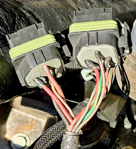
I took both FP & ICC relays out and now forgot which ones go where. Can you tell me which relay is which based on the photo's?
|
Posted By: KENO
Date Posted: August-14-2024 at 5:47pm
|
The fuel pump relay socket has the green/yellow wire going to it. Which leads back to the question of do you have the 310 page manual? You can figure out lots of stuff with it, like what color wires go to which relays If you click on the link below, you'll have it http://correctcraftfan.com/downloads/PCM_GT-40_Service_Manual.pdf" rel="nofollow - link There are quite a few discrepancies but it's better than not having one at all |
Posted By: Grover
Date Posted: August-14-2024 at 8:14pm
|
Yes, I have the manual. Also, couldn't figure out how to delete my original post? Mark |
Posted By: KENO
Date Posted: August-15-2024 at 7:24am
 In that post, follow the Green arrow in the picture, click on Post Options and you'll see a dropdown with delete post as an option......click on that and it's gone. That option doesn't show up if there's a post after yours in the thread.
|
 Grover wrote:
Posted By: Grover
Date Posted: August-25-2024 at 1:05pm
|
I was getting ready to begin my "no-start" checklist I put together and ran into a problem right away with the 8-Pin connector on the back of the engine and need advice how to proceed. It seems that I am missing a pin on the male side of the 8-pin connector...or, maybe it's not supposed to be there in the first place. My guess is that the orange wire is supposed to combine with the red wire on this side of the plug and has something to do with alternator charging the battery. Do you know if these connectors are still available for purchase or something equivalent? 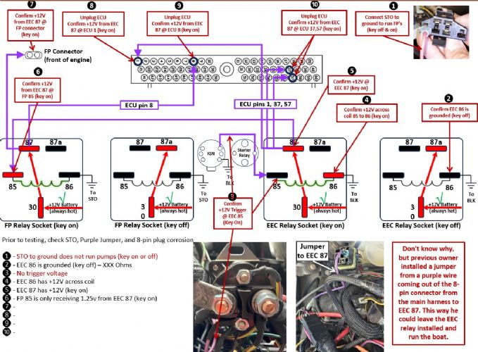 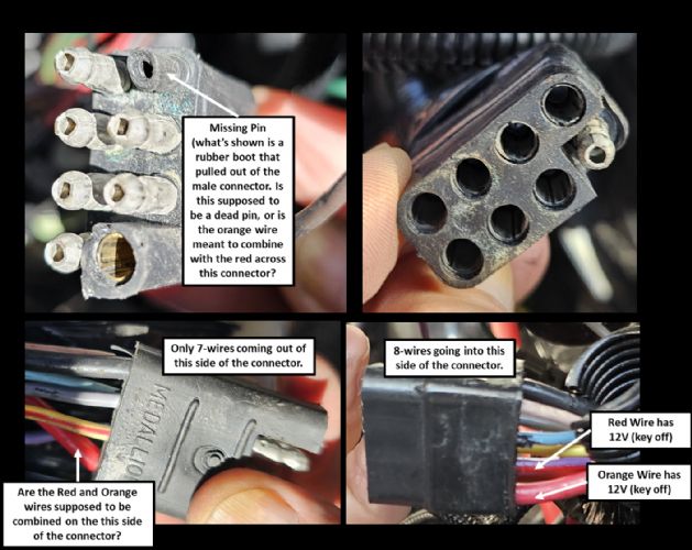 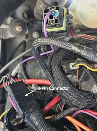 |
Posted By: KENO
Date Posted: August-25-2024 at 2:04pm
|
You're on a roll here......the 8 wires in and 7 wires out at the connector is normal on your boat. The Orange wire that's missing would have been for a boat with an ammeter in the dash. Ammeters disappeared in the early to mid eighties. Kinda a repeat of earlier, your pumps not running with the STO jumpered stil tells me that you don't have a computer issue and that the problem is the wire from the ECM 87 to FP 85. Your diagrams and readings seem to back this up I'd do some untaping of the harness and run a new wire and/or replace the FP relay socket. And........check your PM's |
Posted By: Grover
Date Posted: August-26-2024 at 2:42pm
Keno, thanks again for guiding me thru this troubleshooting. I did a quick check of the EEC relay w/ key-on and found that EEC 85 (Lrg Brn wire) is only getting between 6 to 8+ volts and keeps jumping around on the VOM. Do you know where this wire goes and how to trace it?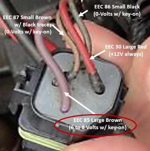 |
Posted By: KENO
Date Posted: August-26-2024 at 3:53pm
|
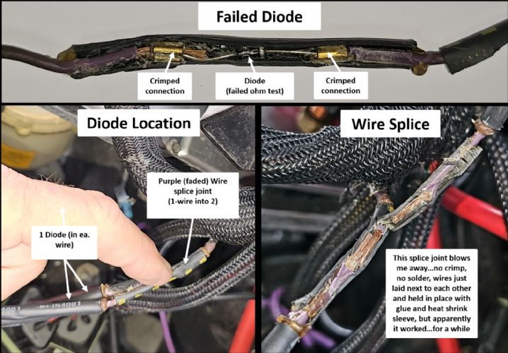
Every once in a while, with more pictures and explanations to look at, you have a Eureka moment..... this might be one of those moments. I think you need to read the link below to a thread on Planet Nautique and find the diode he's talking about and replace it. (he has basically the same thread here on CCF, but the pictures disappeared from the CCF thread) You could temporarily jumper around it, put both relays back in, with the previous owner's jumper removed, turn the key and see if it starts The pictures he has are real helpful for location and the explanation is really good too.
http://www.planetnautique.com/vb5/forum/nautique-topics/maintenance-technical-discussion/591096-1997-gt40-suddenly-quits-intermittently" rel="nofollow - link I think that explains your low voltage to the EEC relay and the jumper that the PO put in supplied the correct voltage to the EEC and fuel pumps with the key in Start or Run, by bypassing that diode in a pretty roundabout manner. The diode is #12 in the diagram on page 6-8 of the big manual.
|
Posted By: Grover
Date Posted: August-26-2024 at 5:51pm
One more thought, instead of trying to find that diode, can I do what's shown below...???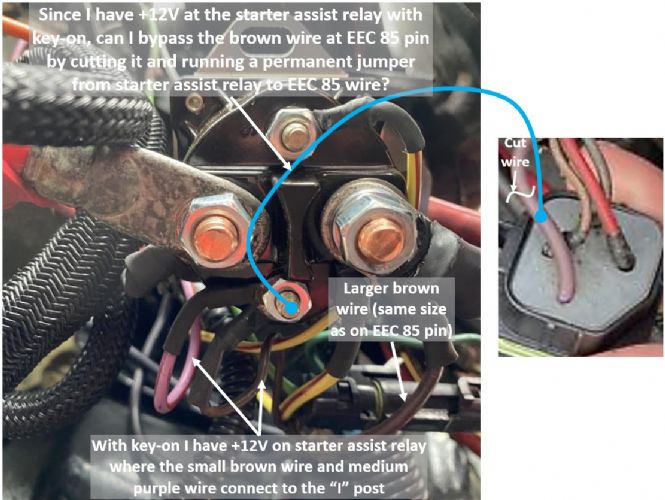 |
Posted By: KENO
Date Posted: August-26-2024 at 8:16pm
|
I fixed my screwed up link in the previous post. The diode is in the wire hooked to the "I" terminal, so if you do your bypass, it's basically doing the same thing without a diode. I'd give it a shot and assuming it works, get a diode like in the link and put that in (or now that you should be able to see the pictures in the link, find the diode and replace it) PS I think your arrow is pointing at the Purple wire that goes to the EEC relay pin 85 and like you said, that's the one you want to cut for your bypass.
|
Posted By: Grover
Date Posted: August-27-2024 at 7:01pm
|
Posted By: KENO
Date Posted: August-27-2024 at 8:22pm
|
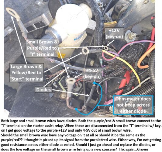
Pictures along with some words are a wonderful thing Like your last picture for example......if your assist relay is wired the way you describe, then it's not wired right. Here's an earlier picture of yours that only shows one wire on the "S" terminal but other connections had me wondering if the wiring to the starter was right.  Here's a PCM diagram to look at. One thing to keep in mind is that 28 year old faded purple wire can look pretty brown  And a hand drawn version from a 2000 gt40 engine, no Brown wires but faded, discolored Purple
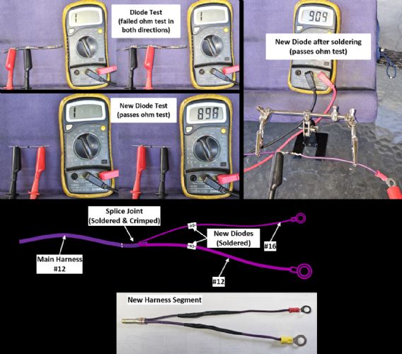
https://ibb.co/QMT98zR" rel="nofollow">  It may scramble your brain, but that's the right wiring for a PMGR Ford starter on your engine. Testing the diodes.....Red lead hooked to the lug and Black lead to the downstream side of the diode through a small break in the wire insulation should show continuity and then if you reverse the leads it should show infinite resistance. Infinite in both directions is telling you the diode is bad I'd do the jumper around the diode that you were thinking of and see if everything works as it should or since you're this far, go ahead and get new diodes and replace them. |
Posted By: Grover
Date Posted: September-17-2024 at 8:20pm
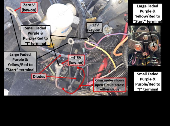
correction of previous image...
     |
Posted By: KENO
Date Posted: September-18-2024 at 8:32am
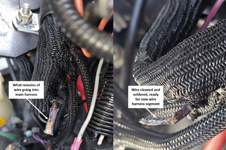
You should be giving yourself a big  , you did all the hard work. , you did all the hard work.And you put up some good diode and splice pictures too
|