 Boats For Sale:


1990 Dash Wiring |
Post Reply 
|
Page <123> |
| Author | |
TX Foilhead 
Grand Poobah 

Joined: February-01-2009 Location: Kingsland TX Status: Offline Points: 2076 |
 Post Options Post Options
") Thanks(0) Thanks(0)
 Quote Reply Quote Reply
 Posted: June-10-2011 at 3:01pm Posted: June-10-2011 at 3:01pm |
|
Duplex wire is just 2 wires that have a cover around both, it's handy because you only have to pull 1 thing. Like Eric said, it's like plumbing so I did both sides. After some discussion on other boards I decided to get my hot from the 50 amp breaker. Never saw a good explanation, but the general consensus was the 50 amp breaker protects the wiring to the dash should something go wrong with the alternator or the battery.
|
|
 |
|
|
MinaquaWI
Newbie 
Joined: May-02-2011 Location: Hudson, WI Status: Offline Points: 25 |
Post Options
Thanks(0)
Quote Reply
Posted: June-10-2011 at 3:11pm |
I second this. And at $3 a foot for wire, it saved me an extra $15 since the battery is under the rear seat in the sport. If you ran to the battery, I would add a fuse there but this means more connections. |
|
|
Current - 1991 Sport Nautique, 1970 Glastron GT-140, 1970's MasterCraft Jump Boat
|
|
|
|
|
Daveinater
Senior Member 

Joined: May-15-2007 Location: Senoia, Georgia Status: Offline Points: 264 |
Post Options
Thanks(0)
Quote Reply
Posted: June-10-2011 at 3:12pm |
|
Nick,
OOPS...duh...I see a scroll bar too. (Pretty lame for a self-professed computer geek. Sorry). Still, it would be nice to have a copy of the diagrams e-mailed if possible. Didnt see your e-mail in your profile so here's mine: Four-Bucks at att dot net As for the duplex link you provided, it's broken so you may want to double-check it. When you e-mail I will confirm exactly where you ran that duplex from and to, so I dont have to beat a dead horse with everyone watching...hahah 
|
|
|
Dave B.
Our 1992 Sport Nautique |
|
|
|
|
MinaquaWI
Newbie
Joined: May-02-2011 Location: Hudson, WI Status: Offline Points: 25 |
Post Options
Thanks(0)
Quote Reply
Posted: June-10-2011 at 3:23pm |
|
Dave, if you do a google search for duplex at west marine, it comes up right away. Like I said earlier, I used 8ga, but if I did it again, I would use 10ga. 8ga connectors are hard to find and it's thick wire to work with. If you are ambitious or running high power amps or accessories, maybe 8 ga would make you feel better though.
|
|
|
Current - 1991 Sport Nautique, 1970 Glastron GT-140, 1970's MasterCraft Jump Boat
|
|
|
|
|
TX Foilhead
Grand Poobah
Joined: February-01-2009 Location: Kingsland TX Status: Offline Points: 2076 |
Post Options
Thanks(0)
Quote Reply
Posted: June-10-2011 at 3:53pm |
|
Amps shouldn't run off the dash wire, maybe the head unit, but it's best to keep the stereo all connected to the same battery bank if you can to keep the noise out. I've been lucky with mine and never had an issue, but I'm very careful about making sure everything is connected to the same ground, the new bus makes that easy. There's enough. screwy things going on with marine stereos, don't add one.
|
|
|
|
|
8122pbrainard
Grand Poobah

Joined: September-14-2006 Location: Three Lakes Wi. Status: Offline Points: 41040 |
Post Options
Thanks(0)
Quote Reply
Posted: June-10-2011 at 3:59pm |
Load side of the main breaker for the + feed and engine block for the -. Then, I prefer up to added terminal strips under the dash so you csn branch off from them instead of trying to tap into the existing daisy chains. The terminal strips also give you more room for future add-ons. Solderless ring terminals for 8ga are not hard to find but I suggest getting the ones with the heat shrink insulation on them. Good old McMaster has them. 8ga, by # 10 stud ring terminals |
|
|
|
|
Daveinater
Senior Member
Joined: May-15-2007 Location: Senoia, Georgia Status: Offline Points: 264 |
Post Options
Thanks(0)
Quote Reply
Posted: June-10-2011 at 4:45pm |
Thankfully I ran my two Alpine PDX 4.150 amps and Infinity Kappa Perfect sub all off seperate 6-guage wiring from the battery, with their own fuse blocks, etc. I cant rememeber if I rewired the head unit off of that same circuit but I believe I did. So my main issue is the factory guages/indicators. Thanks for all the great advice everyone. |
|
|
Dave B.
Our 1992 Sport Nautique |
|
|
|
|
WakeSlayer
Grand Poobah

Joined: March-15-2006 Location: United States Status: Offline Points: 2138 |
Post Options
Thanks(0)
Quote Reply
Posted: June-10-2011 at 4:52pm |
|
OK. I have been putting off fixing my weak ground on my SAN for long enough. I have been stalling for 6 years.
I have a 2 ga. power and ground cable from my batteries to terminal blocks, and then they branch to my amplifiers. Is there any reason I cannot simply tag an 8 ga. ground wire from the ground block to my ignition, rather than going all the way back to the batteries? If I elect to run an additional power wire, I would come off the perko. Sorry, still 12V challenged for the most part. thanks |
|
|
Mike N
1968 Mustang |
|
|
|
|
TX Foilhead
Grand Poobah
Joined: February-01-2009 Location: Kingsland TX Status: Offline Points: 2076 |
Post Options
Thanks(0)
Quote Reply
Posted: June-10-2011 at 5:34pm |
|
I don't see a problem with the ground wire if all you batteries are grounded to that spot and it's grounded to the motor. I do try and make my wiring easy for someone else to figure out so you might want to do the same for a future owner or someone working on it. The problem with wiring to the Perko switch would be that wire is connected straight to the battery and might not be fused. I've burnt up a couple of wiring harnesses on other things and it's a PITA to have to clean up and redo. I'm also not real clear how the newer boats are wired, so you might want to look over the diagrams before you start. I spent a few nights looking at the diagrams, and searching online before I decided what to do. Then I ran it buy a couple of engineers at work just to make sure my thinking was right. It's not that hard once you look at it a spend a little time figuring it out.
|
|
|
|
|
WakeSlayer
Grand Poobah
Joined: March-15-2006 Location: United States Status: Offline Points: 2138 |
Post Options
Thanks(0)
Quote Reply
Posted: June-10-2011 at 6:16pm |
|
I went and got some 10ga wire and a couple appropriate ring terminals at lunch. I am just going to do the ground first and see how that works. If that is not the complete solution, then I will run a wire from the perko, and definitely fuse it. I am 12v challenged, but not that much so.
thanks Mike |
|
|
Mike N
1968 Mustang |
|
|
|
|
Daveinater
Senior Member
Joined: May-15-2007 Location: Senoia, Georgia Status: Offline Points: 264 |
Post Options
Thanks(0)
Quote Reply
Posted: June-10-2011 at 6:18pm |
|
Mike,
I think I am alot more well versed in 12v that you so I'll just warn you now---make sure the battery is off or you will totally fry yourself. 
Good luck! Dave P.S. Let me know how the new wire changes things. My boat is 2 hr drive away so I have to prep for this and hope to do mine within the next week or so. |
|
|
Dave B.
Our 1992 Sport Nautique |
|
|
|
|
TX Foilhead
Grand Poobah
Joined: February-01-2009 Location: Kingsland TX Status: Offline Points: 2076 |
Post Options
Thanks(0)
Quote Reply
Posted: June-10-2011 at 7:04pm |
|
I don't see a problem with the ground wire if all you batteries are grounded to that spot and it's grounded to the motor. I do try and make my wiring easy for someone else to figure out so you might want to do the same for a future owner or someone working on it. The problem with wiring to the Perko switch would be that wire is connected straight to the battery and might not be fused. I've burnt up a couple of wiring harnesses on other things and it's a PITA to have to clean up and redo. I'm also not real clear how the newer boats are wired, so you might want to look over the diagrams before you start. I spent a few nights looking at the diagrams, and searching online before I decided what to do. Then I ran it buy a couple of engineers at work just to make sure my thinking was right. It's not that hard once you look at it a spend a little time figuring it out.
|
|
|
|
|
WakeSlayer
Grand Poobah
Joined: March-15-2006 Location: United States Status: Offline Points: 2138 |
Post Options
Thanks(0)
Quote Reply
Posted: June-10-2011 at 7:20pm |
|
Dave
The batteries won't even be connected if I go to the positive side. Perko off for the ground addition, though I don't think it needs to be. |
|
|
Mike N
1968 Mustang |
|
|
|
|
Daveinater
Senior Member
Joined: May-15-2007 Location: Senoia, Georgia Status: Offline Points: 264 |
Post Options
Thanks(0)
Quote Reply
Posted: June-10-2011 at 7:22pm |
|
Mike,
That was my lame attempt at humor. Don't listen to a word I say.
(When you're done, you can do my boat). Have a good weekend, Dave |
|
|
Dave B.
Our 1992 Sport Nautique |
|
|
|
|
Bri892001
Grand Poobah

Joined: September-27-2008 Location: Boston MA Status: Offline Points: 4945 |
Post Options
Thanks(0)
Quote Reply
Posted: June-13-2011 at 2:52pm |
|
Sorry, I was offline all weekend.
After reading everything above, I'll just mention that these boats don't typically come with a ground bus, hence the wacky daisy chained ground. It would be possible to wire a ground bus in, and that could be a great improvement, just a little bigger project. You could have all of your instruments and accessories, and maybe the original factory harness ground go to the bus, and add your new wire to the bus as well. That would probably be even better than what I did, but it would mean a complete re-wiring of the ground side of your dash. |
|
|
|
|
Daveinater
Senior Member
Joined: May-15-2007 Location: Senoia, Georgia Status: Offline Points: 264 |
Post Options
Thanks(0)
Quote Reply
Posted: June-20-2011 at 11:21am |
|
All,
Just wanted to give a quick updated on MY dash wiring project. First off, special thanks to Nick for his awesome wiring diagram. I'm especially impressed that he took the time to figure it out after my personal look under the dash. I didn't take any photos but just a few things to note: My 1992 Sport did not have a "daisy chain" like was noted in Nick's post. Instead, it had the engine ground to a butt splice (it looked factory) which then went to two one large grouping of wires, each into a very large butt splice (again, it was factory). The first butt splice had all the grounds for the dash switch "ON" indicator lights (next to each C/B switch). Off of that splice, there was one jumper wire which went to the second large butt splice which had all the grounds for most of the instrument cluster. Additionally, the ground wires for a couple smaller harnesses were tapped in to the instrument cluster grounds via butt splices. A mechanic buddy of mine made a very nice buss bar and soldered some heavy duty jumpers between all the contacts on one side and made a 10 gauge "feeder wire" into that side, with a butt splice, where I attached the new ground wire from the engine (just like Nick did). I screwed the buss bar to the side panel under the dash to keep it secured. I then took the few odd rogue ground wires, snipped each, installed a ring terminal and fed it direct to that buss bar. I snipped the jumper between the two large butt splice junctions and fed each butt splice to the buss bar as well. I started the boat and viola! No weird indications, no "jumps" when the lights were turned on and my voltmeter reads a steady 14 volts! (It never read above 10 v but I knew the alternator was doing it's job since I tested it with a voltmeter). Additionally, after running the boat all weekend, I discovered that my "warm operating temperature" issues were ground-related as well. Instead of running 160-180 (and close to 190-200 at times), it ran 140-160 (and never above) all weekend. Lesson learned: These boats seem prone to bad ground issues. If you're chasing down some weird indications, start there first! Again, thanks to Nick for his hard work, diagrams and post which inspired me to (finally) attack this, and to the rest of you who added in valuable information. |
|
|
Dave B.
Our 1992 Sport Nautique |
|
|
|
|
Bri892001
Grand Poobah
Joined: September-27-2008 Location: Boston MA Status: Offline Points: 4945 |
Post Options
Thanks(0)
Quote Reply
Posted: June-20-2011 at 12:48pm |
 Sounds like you hit a grand slam with the bus bar. I think that's ultimately the way to go to get it all 100% Sounds like you hit a grand slam with the bus bar. I think that's ultimately the way to go to get it all 100%
|
|
|
|
|
MinaquaWI
Newbie
Joined: May-02-2011 Location: Hudson, WI Status: Offline Points: 25 |
Post Options
Thanks(0)
Quote Reply
Posted: June-20-2011 at 6:07pm |
|
Dave that's great!
|
|
|
Current - 1991 Sport Nautique, 1970 Glastron GT-140, 1970's MasterCraft Jump Boat
|
|
|
|
|
gjsullivan
Newbie

Joined: November-08-2004 Location: Hillsboro, OR Status: Offline Points: 13 |
Post Options
Thanks(0)
Quote Reply
Posted: August-24-2011 at 4:12am |
|
OK here is how you see the whole diagrams.
right click on a diagram. You can do a save as and save it as a jpg file that you can then open and print. Or you can right click, copy and paste it into a word doc. set the page to landscape and save the doc. Thanks for doing this. I drew my entire wiring diagram. Had it for 10 years and lets just say the diagram disappeared last week.( I should have made a copy :-( oh well ) I have the leaking voltage problem and we were going to try and track it down, but without the wiring diagram it would take a while. Can you provide the source files you used to draw the diagrams. I have some custom wiring I have done and would need to modify what you have. Thanks for all the work laying out the wiring. Glenn gjsullivan@juno.com |
|
|
67 Mustang, 90 Sport
|
|
|
|
|
storm34
Grand Poobah

Joined: November-03-2008 Location: Dexter Iowa Status: Offline Points: 4492 |
Post Options
Thanks(0)
Quote Reply
Posted: August-24-2011 at 12:40pm |
|
Threadjack...
Nick, lets see some pics of that jump boat!!! |
|
|
|
|
Airgrabber
Senior Member

Joined: August-16-2011 Location: Indiana Status: Offline Points: 163 |
Post Options
Thanks(0)
Quote Reply
Posted: August-24-2011 at 3:02pm |
|
As for added a relay to your starter that’s a good idea because as the contacts in the ignition switch can only handle so much current. It’s like having a resistor in the circuit if your contacts are getting burnt or bad. I do that in a lot of older cars that I’ve rewired because the ignition wires run through the switch. As for voltage drop you should have the same voltage reading from the regulator threw the whole circuit. If there is a voltage drop to any of the components it can be several issues, to small wire, bad connections, and loose terminals. Look at all the wires and connections make sure they are not discolored. Also over sizing you wire by a couple of gauges will definably not hurt anything especially if you adding a stereo. Take an amp reading at the regulated 12 volts and make sure not drawing more that what the alternator is rated at.
|
|
|
Life is good. Work hard! Play Hard!
|
|
|
|
|
gjsullivan
Newbie
Joined: November-08-2004 Location: Hillsboro, OR Status: Offline Points: 13 |
Post Options
Thanks(0)
Quote Reply
Posted: August-24-2011 at 11:15pm |
|
Nick,
Are these drawings had drawn on paper ? |
|
|
67 Mustang, 90 Sport
|
|
|
|
|
gjsullivan
Newbie
Joined: November-08-2004 Location: Hillsboro, OR Status: Offline Points: 13 |
Post Options
Thanks(0)
Quote Reply
Posted: August-30-2011 at 3:17am |
|
Nick,
The blue wires you have going to the instrument lights do not have a connection to power. I think you need to bring a connection down to a light switch. Glenn |
|
|
67 Mustang, 90 Sport
|
|
|
|
|
SNobsessed
Grand Poobah
Joined: October-21-2007 Location: IA Status: Offline Points: 7102 |
Post Options
Thanks(0)
Quote Reply
Posted: July-09-2013 at 8:57pm |
|
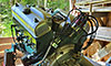
Old thread, but was informative - I finally added the extra hot-feed to the ignition breaker today. I gained about 1/2 volt per the dash voltmeter.
I pretty much followed what was discussed here but I also added a fuse for the new 10 gage wire - my thought was that if the main wire ever was somehow taken out of the circuit, the 10 gage wire would only be protected by the 50 amp breaker (do you smell something burning?) The fuse is tie-wrapped to the breaker bracket: 
|
|
|
“Beer is proof that God loves us and wants us to be happy.”
Ben Franklin |
|
|
|
|
drekeith
Newbie
Joined: July-07-2015 Location: US Status: Offline Points: 16 |
Post Options
Thanks(0)
Quote Reply
Posted: July-07-2015 at 7:09pm |
|
Hello...I love the diagram and it looks similar to my 1994 sport nautique.. I am no electrician (but can do some wiring). I simply want to run my new radio from a spare acc breaker because currently it runs from the clock (as you would know) and at louder volumes my radio goes into safe mode "or just shuts off" I suspect it is drawing down too much amperage through the smaller wire that runs form the clock when i turn it up but I would like to simply require so that it is on acc 3 or 4. Can you guide me on where to connect my new hot wire and ground (also running from the clock). Also, what about the current yellow wire that runs form the ignition (or I can just leave that one I guess?)
Thank you! |
|
|
KD
|
|
|
|
|
spiralhelix
Senior Member
Joined: August-06-2014 Location: IL/WI Status: Offline Points: 496 |
Post Options
Thanks(1)
Quote Reply
Posted: July-07-2015 at 7:22pm |
|
the top sides of the breakers are all daisy chained together, so you can attach your 12v ig wire from the stereo to the bottom part of the breaker. The preferred method for adding the ground is to use a negative bus bar, but you can just pigtail the stereo ground with the others. Not sure if i have seen much discussion on the 96, but a lot of people have run new power to the ig breaker and a new ground, both increasing the size from 14 gauge to 10 gauge.
Not familiar with the yellow wire, so I can't comment on that without looking at a diagram. -Spiral UPDATE: I just looked at the diagram on the first page. You shouldn't have to do anything with the yellow wire. Seems odd they even wired the stereo off the clock to begin with. In a car, the ignition acts as the switch for the stereo, but when using the acc switch, that will do the same thing, so you don't need to wire the stereo to the ignition key. |
|
|
|
|
flyweed
Gold Member 
Joined: July-11-2016 Location: WI Status: Offline Points: 539 |
Post Options
Thanks(0)
Quote Reply
Posted: September-07-2016 at 8:55pm |
|
Sorry to dredge up an old thread..but I am wondering if ANYONE knows of a dash wiring diagram for a 1993 SN? Is it the same as the 1990??
I am going to dig in and replace some non working backlights in a few gauges, maybe pull a new 10 gauge ground wire from the engine, and stuff like that. a diagram for the back would be great. Thanks for any thoughts, help, etc. |
|
|
'93 Ski Nautique NWZ, Air Boom Tower
Drink Tonight..for tomorrow We Ride! |
|
|
|
|
Bri892001
Grand Poobah
Joined: September-27-2008 Location: Boston MA Status: Offline Points: 4945 |
Post Options
Thanks(0)
Quote Reply
Posted: September-07-2016 at 10:21pm |
|
The logic for the 93 is basically the same as the diagram for the 89 that you'll find under reference > miscellaneous on this site.
|
|
|
|
|
Bri892001
Grand Poobah
Joined: September-27-2008 Location: Boston MA Status: Offline Points: 4945 |
Post Options
Thanks(1)
Quote Reply
Posted: September-07-2016 at 10:24pm |
|
Here's the work I did on my 93, plus work others did to theirs as well;
http://www.correctcraftfan.com/forum/forum_posts.asp?TID=21901 |
|
|
|
|
flyweed
Gold Member
Joined: July-11-2016 Location: WI Status: Offline Points: 539 |
Post Options
Thanks(0)
Quote Reply
Posted: September-07-2016 at 11:13pm |
|
thanks much. I read through your thread..and will be adding the extra ground and hot runs from the engine to the dash.
|
|
|
'93 Ski Nautique NWZ, Air Boom Tower
Drink Tonight..for tomorrow We Ride! |
|
|
|
|
Post Reply
|
Page <123> |
 Tweet
Tweet
|
| Forum Jump | Forum Permissions You cannot post new topics in this forum You cannot reply to topics in this forum You cannot delete your posts in this forum You cannot edit your posts in this forum You cannot create polls in this forum You cannot vote in polls in this forum |


 Topic Options
 TX Foilhead wrote: