 Boats For Sale:


Ignition wiring only. |
Post Reply 
|
| Author | ||
KENO 
Grand Poobah 
Joined: June-06-2004 Location: United States Status: Offline Points: 11112 |
 Post Options Post Options
") Thanks(0) Thanks(0)
 Quote Reply Quote Reply
 Topic: Ignition wiring only. Topic: Ignition wiring only.Posted: May-22-2021 at 7:12am |
|
The engine to dash harness would be in the link below with their note that the dash end will have to be cut and hardwired, but that's no big deal to do. |
||
 |
||
|
KENO
Grand Poobah
Joined: June-06-2004 Location: United States Status: Offline Points: 11112 |
Post Options
Thanks(0)
Quote Reply
Posted: May-22-2021 at 7:01am |
|
|
Here's a link to the Arco starter. The list price is shown, but a little shopping will find them for 150 bucks or so at many places  |
||
|
||
|
wayoutthere
Senior Member 
Joined: February-28-2020 Location: Florida Status: Offline Points: 477 |
Post Options
Thanks(0)
Quote Reply
Posted: May-22-2021 at 7:01am |
|
|
Thank you keno,
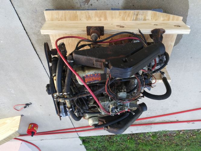
There was no pin on the engine or dash side harness, it was all crimped taped jumped and hacked together. The whole harness was cut loose and trashed minus what you see on the engine. The gauges were trashed as well, the new gauge package has a volt meter and is standard analog. Was on skidim last night and seen the upgraded starter for this engine, they also have complete distributor w/ the correct coil. Didnt know about internal/external isolated alternators so i will get some numbers off it for when i call skidim on monday. If skidim has both sides of the harness it would save alot of time as scratch built harnesses are a labor of love. I think between all the help from you guys, new part tech help and skidim the harness will be 100%, the engine will fire and run good, hopefully there won't be any electrical gremlins to sort out. Will defineately update you after the skidim order. Thank You. |
||
|
||
|
KENO
Grand Poobah
Joined: June-06-2004 Location: United States Status: Offline Points: 11112 |
Post Options
Thanks(0)
Quote Reply
Posted: May-22-2021 at 6:42am |
|
|
Since you mentioned needing a new starter, a good choice would be the newer PMGR type Ford starter. it's smaller, lighter, more powerful and draws less current.
Arco 70201 would be the part number for a reverse rotation 351 which is what your boat came with, but it would be good to verify the rotation before ordering a new starter. Here's a drawing similar to the previous one, that shows the wiring a little better at the ballast resistor and shows the wiring for the PMGR starter which is a little different from the solenoid{starter relay} to the starter itself. You'll have to rotate it and enlarge it 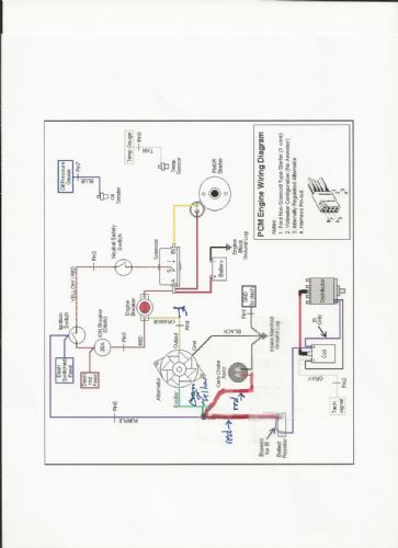 |
||
|
||
|
KENO
Grand Poobah
Joined: June-06-2004 Location: United States Status: Offline Points: 11112 |
Post Options
Thanks(0)
Quote Reply
Posted: May-21-2021 at 7:12pm |
|
|
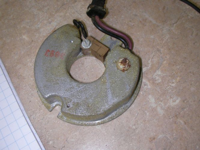
It looks to me like you have a Prestolite distributor with a screwdown cap like you said.
The module is a Prestolite module that's been out of production for a long time. The alternator is a little hard to tell, but it looks like a Motorola or Mando from the 80's. They're basically the same alternator. They're internally regulated. If you were to unplug the engine harness at the 8 plug connector and trash it all and replace it with the engine harness in the link below, life would be a lot easier. The price isn't terrible for what you get. It works for your alternator and distributor but it's for a voltmeter setup not an ammeter. It gives a lot shorter more direct charging path to the battery with the ammeter deleted. You'll probably have questions about the Red and Orange wires to the dash, or other questions too, but just ask  The directions with the harness "leave a little to be desired" but if you were to follow the diagram below, you'd be doing good. 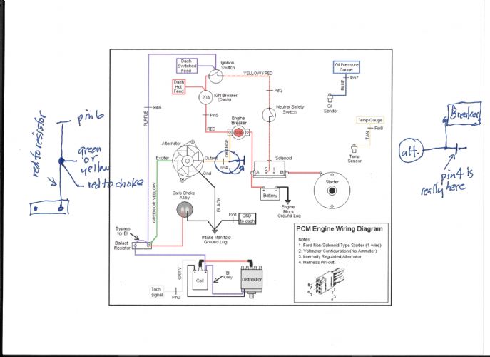 The alternator, ignition wire, choke wire connection can be at the ballast resistor or later on it was inside the wiring harness as shown.
|
||
|
||
|
Wilhelm Hertzog
Senior Member
Joined: June-14-2014 Location: Cape Town Status: Offline Points: 334 |
Post Options
Thanks(0)
Quote Reply
Posted: May-21-2021 at 3:57pm |
|

|
||
|
1982 Ski Nautique PCM351W RR II Velvet Drive 10-17-003 1:1 II PerfectPass Stargazer
Do not go gentle into that good night. Rage, rage against the dying of the light. |
||
|
||
|
wayoutthere
Senior Member
Joined: February-28-2020 Location: Florida Status: Offline Points: 477 |
Post Options
Thanks(0)
Quote Reply
Posted: May-21-2021 at 2:52pm |
|
I dont think jeff would care, i guess correctcraft and planetnautique compete over advertising ? , but share members, it would suprise me if help wasn't coming from that direction to rebuild this site in some way. He turns those boats around pretty good, that yellow and silver one is the tops There was an ammeter in the dash, and the dash was all hacked and spliced too ! which makes me think generator, wires spliced, some kinda Big Jimbo Boat Repair going on. It looks like an alternator, its a screw down dist cap which from what i read is prestolite. I figured a mercruiser smartcraft ski engine would pop up along the way and this build would be plug and play. That said, I am all for new electric components if needed, it already needs a starter, it just doesn't need anymore Big Jimbo Boat Repair
|
||
|
||
|
wayoutthere
Senior Member
Joined: February-28-2020 Location: Florida Status: Offline Points: 477 |
Post Options
Thanks(0)
Quote Reply
Posted: May-21-2021 at 2:45pm |
|
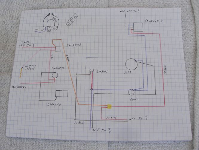 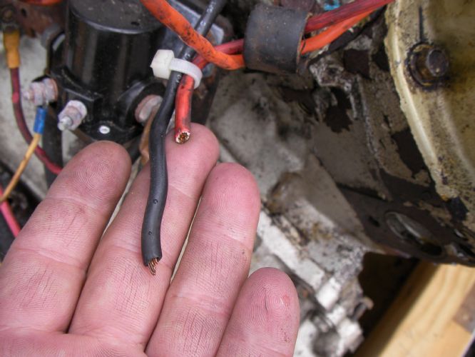  The pictures holding the wires correspond to the drawing where i noted "off to ?" as in are they going to or coming from somewhere. The pictures holding the wires correspond to the drawing where i noted "off to ?" as in are they going to or coming from somewhere.
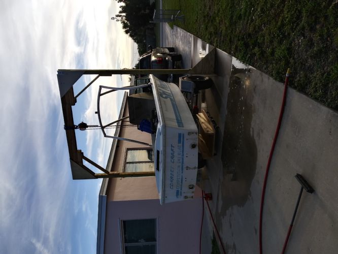
I literally need it from a to b, from b toc, etc etc. Since it was converted from point to electric along with all the hokey splicing on the engine and dash adds to the belief it was wired to run but not neccessarily correct or safe as the yellow butt joint spliced thing is melted. Any and all advice is greatly appreciated 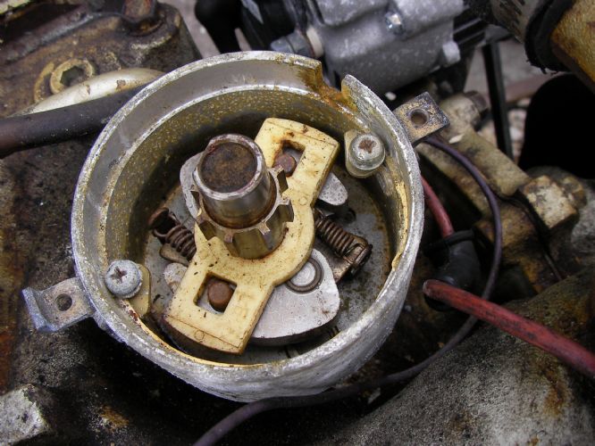 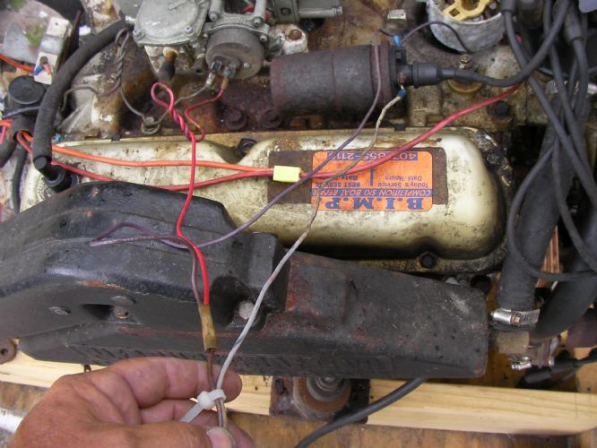 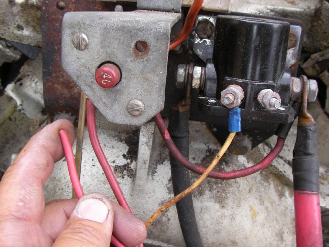 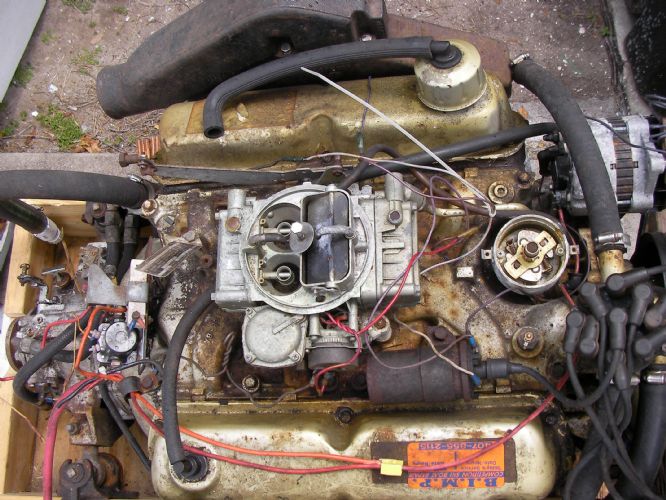 Below is where the engine is, 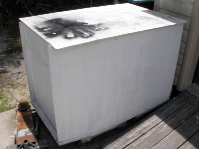 This is what is like when i open the box https://youtu.be/XBIZQcVMaNo |
||
|
||
|
wayoutthere
Senior Member
Joined: February-28-2020 Location: Florida Status: Offline Points: 477 |
Post Options
Thanks(0)
Quote Reply
Posted: May-21-2021 at 2:21pm |
|
I was hanging upsidedown from ole rickety when that pic was taken, this one i was laying on the deck of the raceboat, that one i was falling off the ladder 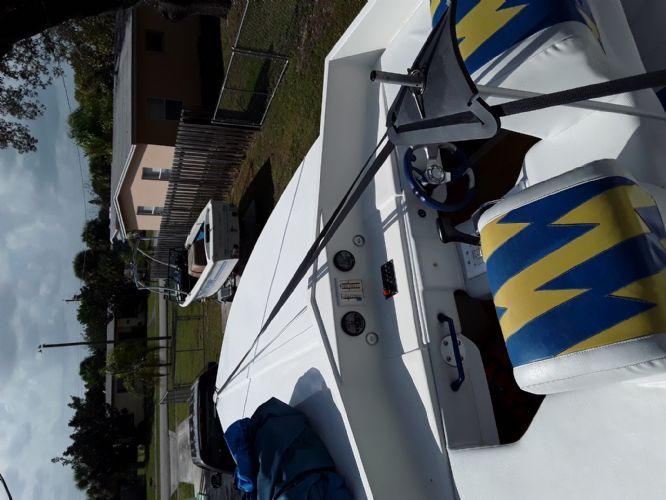 |
||
|
||
|
KENO
Grand Poobah
Joined: June-06-2004 Location: United States Status: Offline Points: 11112 |
Post Options
Thanks(0)
Quote Reply
Posted: May-20-2021 at 5:27am |
|
|
But all the other pictures you posted at about the same time in your other thread came out right side up
|
||
|
||
|
wayoutthere
Senior Member
Joined: February-28-2020 Location: Florida Status: Offline Points: 477 |
Post Options
Thanks(0)
Quote Reply
Posted: May-19-2021 at 10:07pm |
|
I think i got it but its showing upsidedown
|
||
|
||
|
KENO
Grand Poobah
Joined: June-06-2004 Location: United States Status: Offline Points: 11112 |
Post Options
Thanks(0)
Quote Reply
Posted: May-19-2021 at 8:36pm |
|
Picture posting.........not exactly easy............just slip a picture or 2 or however many into your PN thread and somebody could copy and paste them over here. I don't think Nautique Jeff will charge any royalty fees or anything like that Before you start with wiring diagrams it would be good to know if you have the original 1979 externally regulated Prestolite alternator, whether you have an ammeter or a voltmeter, otherwise trying to follow one specific diagram can get you all screwed up.
|
||
|
||
|
wayoutthere
Senior Member
Joined: February-28-2020 Location: Florida Status: Offline Points: 477 |
Post Options
Thanks(0)
Quote Reply
Posted: May-19-2021 at 8:21pm |
|
|
Thank you, that was fast and i really appreciate the effort.
i will try to draw this out on paper (flow chart) assuming dash hot feed is accy's, dash switched feed is gauges and purple-green-red @ ballast are spliced with ballast removed. I think i see it.
I will take pics and make a drawing of how it is wired but havent figured out how to post pictures yet. Thank you again |
||
|
||
|
8122pbrainard
Grand Poobah

Joined: September-14-2006 Location: Three Lakes Wi. Status: Offline Points: 41045 |
Post Options
Thanks(0)
Quote Reply
Posted: May-19-2021 at 8:01pm |
|
|
Dan,
Here's a basic wiring diagram (courtesy of Tim) 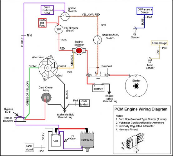 The detail wiring of an EI ignition depends on who made it. How about posting some pictures?
|
||
|
||
|
wayoutthere
Senior Member
Joined: February-28-2020 Location: Florida Status: Offline Points: 477 |
Post Options
Thanks(0)
Quote Reply
Posted: May-19-2021 at 7:22pm |
|
|
1979 nautique,
351 pcm, model PRD WR R10 serial 223571 Screw down distributor cap. At some point before i got the boat it was converted to electric ignition. They spliced and hacked the harness all up, when i unravelled and disected it, some wires had melted. Different size wires were twisted together and electrical taped. On the rear of the engine next to the breaker is a white piece of plastic that i believe is a ballast resistor. There is only 1 wire on it and it was cut and spliced into another bigger wire (from memory it's spliced into 2 wires all twisted together and melted) This conversion has me stumped, i have to make a new complete wiring harness which is not a problem. But; I need a wirring diagram "or route if you will" to start and run the engine every diagram online is points or different year with other electrical components or just to blury to read, and cant identify the name brand to find electronic conversion installation instructions Does it need the ballast or did they just jump it and use the wire on the engine. Thank you I should clarify this, i need from the battery to the engine to the key and back, Everything to start run and charge the engine. Gauges and accy's never get me stumped, it's always the ignition because that always seems to be hacked jumped and made to work somehow, i need it the right way, and im scratch building the harness. Thanks guys |
||
|
||
|
Post Reply
|
|
 Tweet
Tweet
|
| Forum Jump | Forum Permissions You cannot post new topics in this forum You cannot reply to topics in this forum You cannot delete your posts in this forum You cannot edit your posts in this forum You cannot create polls in this forum You cannot vote in polls in this forum |


 Topic Options
 wayoutthere wrote: