 Boats For Sale:


Overcharging the battery |
Post Reply 
|
Page <12 |
| Author | |
KENO 
Grand Poobah 
Joined: June-06-2004 Location: United States Status: Offline Points: 10719 |
 Post Options Post Options
") Thanks(0) Thanks(0)
 Quote Reply Quote Reply
 Posted: August-24-2020 at 4:59pm Posted: August-24-2020 at 4:59pm |
|
|
 |
|
|
8122pbrainard
Grand Poobah

Joined: September-14-2006 Location: Three Lakes Wi. Status: Offline Points: 41040 |
Post Options
Thanks(0)
Quote Reply
Posted: August-24-2020 at 4:49pm |
 How's this Ken?
|
|
|
|
|
KENO
Grand Poobah
Joined: June-06-2004 Location: United States Status: Offline Points: 10719 |
Post Options
Thanks(0)
Quote Reply
Posted: August-24-2020 at 4:46pm |
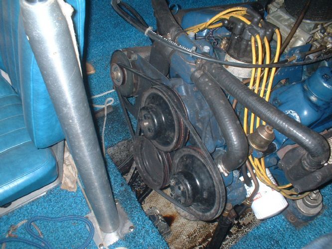
If only this picture showed the wires going into the I A S F connections and the wire colors, Nathan's life would probably be a lot easier Another inch lower with the camera Pete  |
|
|
|
|
8122pbrainard
Grand Poobah
Joined: September-14-2006 Location: Three Lakes Wi. Status: Offline Points: 41040 |
Post Options
Thanks(0)
Quote Reply
Posted: August-24-2020 at 3:44pm |
Is the replacement you put in the same as pictured?
 Was you old regulator putting out the high volts and amps or is it the new one? Was you old regulator putting out the high volts and amps or is it the new one? Before you head down to the lake I suggest compleating the wiring otherwise the regulator isn't going to know how many volts it needs to send to the field. The field controls the aternator output. |
|
|
|
|
NMiles77
Newbie 
Joined: August-22-2020 Location: Ohio Status: Offline Points: 9 |
Post Options
Thanks(0)
Quote Reply
Posted: August-24-2020 at 3:00pm |
|
Gary, Ken thank you for the info. That is the voltage regulator I have on my boat. I got a replacement put it in. I need to take the boat down to the water to test it. The only differences from the diagram on my boat is terminal I is not connected and S is not connected to alternator stator.
|
|
|
|
|
KENO
Grand Poobah
Joined: June-06-2004 Location: United States Status: Offline Points: 10719 |
Post Options
Thanks(0)
Quote Reply
Posted: August-24-2020 at 12:34pm |
|
If your regulator looks like Pete's with I A S and F terminals on it, the picture below sholud explain the hookup to your Motorcraft alternator.
The Motorcraft alternator should have those same connections The big wire on the right of the picture is the 10 gauge output going to the ammeter. The I terminal is fed from the ignition switch Since you put in a DUI distributor the power for the I terminal would come from the same wire that feeds the distributor
 |
|
|
|
|
8122pbrainard
Grand Poobah
Joined: September-14-2006 Location: Three Lakes Wi. Status: Offline Points: 41040 |
Post Options
Thanks(0)
Quote Reply
Posted: August-24-2020 at 7:51am |
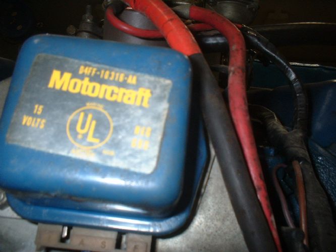 I have the old Motorcraft D4FF-10316-AA And it's wired exactly like the older wiring diagram Ken posted above. I see there are electronic type replacements.
BTW, Gary, I'll have to wait to clean the bilge. Maybe this afternoon the temp will get up and thaw the frozen water in the bilge.  |
|
|
|
|
8122pbrainard
Grand Poobah
Joined: September-14-2006 Location: Three Lakes Wi. Status: Offline Points: 41040 |
Post Options
Thanks(0)
Quote Reply
Posted: August-23-2020 at 8:50pm |
|
I'll take a look at my regulator and report back.
|
|
|
|
|
KENO
Grand Poobah
Joined: June-06-2004 Location: United States Status: Offline Points: 10719 |
Post Options
Thanks(0)
Quote Reply
Posted: August-23-2020 at 8:36pm |
|
Is that the before or after picture Gary?
Nathan has one of those White Escorts. Maybe along with Pete, Orlando76 could also give him some alternator/regulator info since he has an Escort too
|
|
|
|
|
Gary S
Grand Poobah

Joined: November-30-2006 Location: Illinois Status: Offline Points: 14096 |
Post Options
Thanks(0)
Quote Reply
Posted: August-23-2020 at 8:02pm |
|
You may be too late in the season for that. After he spent the last week cleaning the bilge he put the boat away for the year,it is after all the end of August
 |
|
|
|
|
KENO
Grand Poobah
Joined: June-06-2004 Location: United States Status: Offline Points: 10719 |
Post Options
Thanks(0)
Quote Reply
Posted: August-23-2020 at 7:10pm |
|
Nathan
I got your PM about the engine being an Escort conversion with a Motorcraft alternator so the diagram above isn't gonna be right. I'm not sure I've ever seen an Escort wiring diagram I sent a PM to somebody named Pete with an Escort so that he'll look at this thread and he can probably give you some info or pictures
|
|
|
|
|
KENO
Grand Poobah
Joined: June-06-2004 Location: United States Status: Offline Points: 10719 |
Post Options
Thanks(0)
Quote Reply
Posted: August-23-2020 at 7:41am |
 
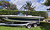
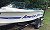
I guess one question should be ......do you have a Pleasurecraft 351, or maybe a Commander or Escort 351 in the boat The info below and the previous diagram pertain to a Pleasurecraft (or Waukesha) engine Here is a non artist's rendition of how the wires hook to the back of a Prestolite alternator on a 76 Pleasurecraft 351 and a picture of a voltage regulator. The 3 blade connector was standard on the engine, so yours has been "modified" over the years if that connector on the regulator has nothing to plug into in the wiring harness. The single wire with the ring connector on the end is purple, maybe yours is red? If you get it wired up right, your charging issue should be resolved. Since you have an ammeter, your big Orange wire goes from the alternator up to the ammeter, to the ignition switch and then back to the solenoid. See the wiring diagram earlier in this thread PS.................I hope the name on the side of the boat is spelled better than you spell it
|
|
|
|
|
NMiles77
Newbie
Joined: August-22-2020 Location: Ohio Status: Offline Points: 9 |
Post Options
Thanks(0)
Quote Reply
Posted: August-22-2020 at 8:49pm |
|
I traced out the green field wire to the alternator. I see the large orange output wire From alternator to the solenoid. I don’t see the black wire from alternator to VR. The new regulator, has red, green, black and ground. Do you have a picture of the correct voltage regulator on back of the engine? The new one came with a connector looks like plug an play. But the original connector is not on my boat.
|
|
|
|
|
KENO
Grand Poobah
Joined: June-06-2004 Location: United States Status: Offline Points: 10719 |
Post Options
Thanks(0)
Quote Reply
Posted: August-22-2020 at 8:23pm |
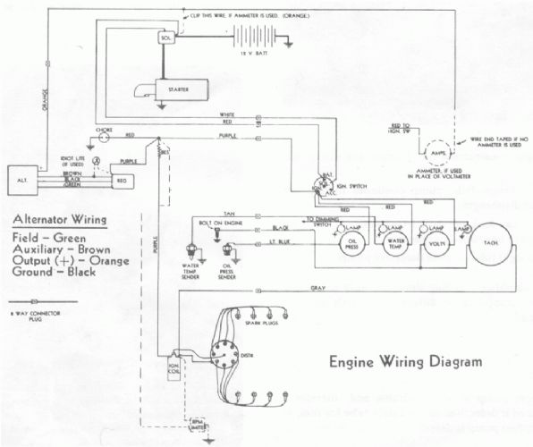 This wiring diagram shows the alternator and external voltage regulator wiring for a 351 Pleasurecraft engine from 1976.Some of the aftermarket regulators had different colors on the wires. Ignore the light on the brown wire, it wasn't used
|
|
|
|
|
NMiles77
Newbie
Joined: August-22-2020 Location: Ohio Status: Offline Points: 9 |
Post Options
Thanks(0)
Quote Reply
Posted: August-22-2020 at 8:09pm |
|
Ok guys I am new to the forum. I have a 1976 Ski Natique. Resently the ammeter has been pegged to +40. There 17 volts across the battery when the engine is running. My thinking is the voltage regulator. The regulator on engine appears not to be original. I have since gotten the original design, however I need a wire diagram. I need to figure out how the original regulator is suppose to be wired. Does anyone have any thoughts?
|
|
|
|
|
Post Reply
|
Page <12 |
 Tweet
Tweet
|
| Forum Jump | Forum Permissions You cannot post new topics in this forum You cannot reply to topics in this forum You cannot delete your posts in this forum You cannot edit your posts in this forum You cannot create polls in this forum You cannot vote in polls in this forum |


 Topic Options
 8122pbrainard wrote: